Announcement

Collapse
No announcement yet.

Intersection lights help

Collapse
X
 
  • Filter
  • Time
  • Show
Clear All
new posts

    Intersection lights help

    I have the installation instructions for a 94 accord intersection and my harness does not look like it, so I figured I had the 93 accord intersection harness, but I am also stumped as to how it connects on the battery side.

    I'm under the assumption that the intersection lights get their power from a 12V source other than the signal lights. But the 12V source is activated when the signal lights are activated. So maybe i am missing a part of the harness? I've looked at all the DIYs. My harness also does not have a negative connection anywhere.

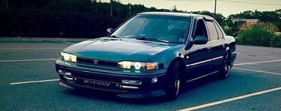
    Looking at the pics on here it looks like the whole harness simply needs a positive and negative? these are my pics of my harness...

    In this picture you can see one wire comes down from the bumper, to the fuse, then one wire back to the relay and then to the 4-prong connector.


    4-prong connector


    Does anyone know how I connect these things?

    #2
    It I really hard to tell from the pictures, it looks like you have 3 't' connectors. Probably one for each turn signal and one for the running light. The ground might pick up from one these lights.

    The 4 pin might go to another harness and then to the fuse box for power and ground. What color wires are in it?
    Manual Belt Conversion-Variable Intermittent Wipers-Steering Volume Controls-Rear Defroster Antenna-JDM Climate Control-MDX Steering Wheel-Lighted Mirror Switch-CL Trunk Solenoid-CL Homelink-Shaved Hood Squirters-Foglight Wiring Diagram-Door Panel Removal-Puddle Lights-Ambient Lighting-Door Speaker Install-Window Seal and Regulator Cleaning-Prelude Cluster-Mirror Tweeter Pods-Illuminated Window Switch -More Coming Soon

    Comment


      #3
      Does anyone have this 4 pin connector on their harness?


      passenger side connector


      drivers side connector #1


      drivers side connector #2


      I just need to know what others have for power wire. Do you have one wire coming from the harness and it goes to power?

      Let's keep in mind I already have the intersection lights connected in the above pictures. My one wire for power goes to a fuse, then to a relay, then to the 4 pin connector. I'm thinking the fuse is the same as the OEM fuse in the fuse box, but I'm not sure what the relay is for....

      Comment


        #4
        Personally, I would say forget the harness and wire up a simple relay circuit from scratch. Which I will be doing with my intersection lights from an RL. /endplug

        Ok after looking at your pictures for a good while, I think I got it.

        Starting at the fuse, that one wire goes straight to the bulb while the other side comes out to the relay. The relay grounds the other side of the light to complete the circuit. I'm not sure how familiar you are with how relays are connected, but you have two wires figured out already:

        -One wire from the relay is connected to the bulb (probably 87)
        -The other has to connect to ground. (30)
        -One end of the coil has to connect to ground (85 or 86)
        -The other is connect to a signal wire to turn the relay on (85 or 86)

        That may be your 4 pins there. I'm not 100% sure.

        YouTube Clicky!!

        Comment


          #5
          Originally posted by sonikaccord View Post
          Personally, I would say forget the harness and wire up a simple relay circuit from scratch. Which I will be doing with my intersection lights from an RL. /endplug

          Ok after looking at your pictures for a good while, I think I got it.

          Starting at the fuse, that one wire goes straight to the bulb while the other side comes out to the relay. The relay grounds the other side of the light to complete the circuit. I'm not sure how familiar you are with how relays are connected, but you have two wires figured out already:

          -One wire from the relay is connected to the bulb (probably 87)
          -The other has to connect to ground. (30)
          -One end of the coil has to connect to ground (85 or 86)
          -The other is connect to a signal wire to turn the relay on (85 or 86)

          That may be your 4 pins there. I'm not 100% sure.
          I have a good understanding of electrical components, wiring, relays, etc. And I see what you are saying here. Basically the relay provides power to the harness (lights) when something is activated. So most likely when power is applied to this relay it allows power to flow through it and activates the intersection lights. The larger relay (in the middle of the harness/bumper) is there to make the lights stay on while the signal lights flash.

          But what I need to know is how others have in their setup. I'm thinking that I can simply cut the wire past the fuse and supply 12V power to it and everything should work when the signal lights come on???

          I am assuming that the OEM setup has 12V > fuse > harness > lights.

          Comment


            #6
            While this unit sits on my table, can anyone think of a way to test this with a 12V source? OR do I need the actual signal lights connected also which supply power to the relay too?

            Comment


              #7
              anyone?

              Comment


                #8
                t=200633http://www.cb7tuner.com/vbb/showthread.php?t=200633

                Not sure if you`ve found this before, or if it helps...
                I have CD5 intersection lights sitting in a box, no harness. Nissan Maxima`s come with them too, can use the controller box from them, so I`ve read/seen.

                Project:Black Skittle

                AOM->April 2014

                MRT->http://www.cb7tuner.com/vbb/showthread.php?t=199779

                Comment


                  #9
                  Yep, seen it. Taking another good look at the picture/sketch and thinking about this a lot more I see some similarities...

                  - Each intersection light has two wires
                  - Each signal light connector has 1 wire leading to it (then another 2 wire connector in-line to connect to the signal light)
                  - I think the 3rd connector drivers side is for the ground, but you can use any end. I think when i got it the connectors were connected which would ground to itself (can't see how that would work)
                  - And past the one lone power wire coming off this, and to the fuse, where it goes to one wire again and then to the relay and 4-pin connector...., I am lost.

                  I'll end testing this when the bumper and car is back together to make it work. I'm betting that I don't need that end relay and 4-pin connector at all.

                  Comment


                    #10
                    worst case scenario, an LM556 circuit and a pair of latching relays will get the job done. (Assuming honda intersection lights are like the cadillacs and buicks, where when the turn signal is on that sides intersection light stays illuminated to see your turn/curb/etc. Ive never seen honda's operate)

                    Comment


                      #11
                      The connectors with grn/blu connects to left turn signal

                      The connectors with grn/yel connects to right turn signal

                      The connectors with red black connects to corner light

                      The 4 pin has
                      Wht/grn. 12v hot from most likely hazard fuse
                      Blk/yel. Ign hot while cranking
                      Blu/red negative from light switch light
                      Blu/yel. ????

                      I can't tell what wire goes where from that picture on the relay. It looks like blk/yel and blu/red are + and - for relay coil. Wht/grn is power feed switched by relay to intersection relay so it only works with both ignition and lights on. Not sure about blu/yel, maybe it is out of the relay back into car harness.

                      What is the pinout of the relay?
                      Manual Belt Conversion-Variable Intermittent Wipers-Steering Volume Controls-Rear Defroster Antenna-JDM Climate Control-MDX Steering Wheel-Lighted Mirror Switch-CL Trunk Solenoid-CL Homelink-Shaved Hood Squirters-Foglight Wiring Diagram-Door Panel Removal-Puddle Lights-Ambient Lighting-Door Speaker Install-Window Seal and Regulator Cleaning-Prelude Cluster-Mirror Tweeter Pods-Illuminated Window Switch -More Coming Soon

                      Comment


                        #12
                        Originally posted by lucifer1 View Post
                        The connectors with grn/blu connects to left turn signal

                        The connectors with grn/yel connects to right turn signal

                        The connectors with red black connects to corner light

                        The 4 pin has
                        Wht/grn. 12v hot from most likely hazard fuse
                        Blk/yel. Ign hot while cranking
                        Blu/red negative from light switch light
                        Blu/yel. ????

                        I can't tell what wire goes where from that picture on the relay. It looks like blk/yel and blu/red are + and - for relay coil. Wht/grn is power feed switched by relay to intersection relay so it only works with both ignition and lights on. Not sure about blu/yel, maybe it is out of the relay back into car harness.

                        What is the pinout of the relay?
                        Appreciate the help everyone. & lucifer that all makes sense. But what is the purpose in plugging a positve/negative in to the corner light? (not like it gets its power from there or a signal)

                        The relay between the fuse and 4-pin connector


                        Now the million dollar question! Has anyone seen this intersection harness and know what plugs into the 4-pin connector?

                        Comment


                          #13
                          That 4 pin connector looks like its for another honda relay.

                          Comment


                            #14
                            Originally posted by illinois_erik View Post
                            worst case scenario, an LM556 circuit and a pair of latching relays will get the job done. (Assuming honda intersection lights are like the cadillacs and buicks, where when the turn signal is on that sides intersection light stays illuminated to see your turn/curb/etc. Ive never seen honda's operate)
                            I was thinking an RC delay circuit that would keep the coil energized during the blinker 'off' time.

                            Is that wire going to the fuse always hot or hot when IGN on? Can you draw a small diagram with the connections?

                            What wire is the other side of the intersection light connected to? There are 5 wires going into a 4-pin harness.
                            Last edited by sonikaccord; 03-26-2015, 07:37 PM.

                            YouTube Clicky!!

                            Comment


                              #15
                              Originally posted by excalibur02 View Post
                              That 4 pin connector looks like its for another honda relay.
                              Ya, I know eh. The red connector would fit in there technically.

                              Originally posted by sonikaccord View Post
                              I was thinking an RC delay circuit that would keep the coil energized during the blinker 'off' time.

                              Is that wire going to the fuse always hot or hot when IGN on? Can you draw a small diagram with the connections?

                              What wire is the other side of the intersection light connected to? There are 5 wires going into a 4-pin harness.
                              Good thought. That would make sense. I think I will only know that answer when I hook it up and see what happens. Can't right now with the battery out of the car, etc.


                              But we all agree (I hope) that the power wire is the lone white one before the fuse and relays, etc. If I were to cut after the fuse and give it 12V, would it work like a OEM one.

                              someone with an OEM harness can tell me where the wire goes after the fuse....

                              Comment

                              Working...
                              X