
I have been noticing a lot more members have been experiencing some type of electrical issues recently. I hope this guide will be of some use to those having said issues.
Dislaimer: I am not responsible for any harm or damage done to self, property, or others. 12v systems are low voltage and it is very unlikely that you will get electrocuted. These systems have high current capability. You can easily set things on fire. Be especially careful near the airbag. It is easy to deploy. It could break your face...We don't want to see a thread in the OT section about you breaking your face..
Note: this will probably be edited several times along with many addendum's. Electrical diagnostics is NOT EASY!! It's a learned skill just like anything else. It won't happen in a day.
You will need a multimeter. It doesn't have to be expensive since you are only using it for two things: Checking voltage and checking continuity. We shall use this 5 dollar meter for this guide: http://www.harborfreight.com/7-funct...ter-98025.html
You will also need the wiring diagrams located here:
http://www.cb7tuner.com/vbb/showthread.php?t=184559
Checking voltages:
To check for DC voltages you would have the pointer in the DCV range on 20. Again, we are working with a 12v automotive system so this range is perfect. When talking about the "range" of a digital multimeter (DMM), we are referring to the placement of the decimal point.
The numbers on the DMM represent the MAX voltage it will read on that setting. The closer you are to the MAX voltage range the more accurate your readings.
Next you insert the black probe into "COM" and the red probe into 'VOhmmA.' The Greek letter Omega is the symbol for Ohms in electrical terms and means resistance. That shall be described in more detail later. DO NOT USE 10ADC!! This is for measuring current. We don't want that now. (If you want, I can describe what that does if it is requested, but for now don't use it.)
Black probe is usually tied to "chassis ground." IOW, it's touching some metal on the car. I like to use alligator clips so I can have a free hand that doesn't have to hold the probe to the chassis. From there, we can use the red probe to check voltages on wires and harnesses. This is the most common setup but there are some occasions where the black probe will have another location.
To check continuity:
Continuity is the setting we choose when we want to check if a wire is connected, broken or shorted. It checks for a "continuous" circuit. For example, a continuous circuit would be a good fuse. If we connect a AA battery to it, it would pass current. An open fuse has no continuity, no current would flow through that open fuse.
Set the meter to the ->|- symbol. This is a schematic symbol for a diode, but it is also good for checking continuity. It usually makes a sound when something has continuity so we don't have to keep looking back at our meter to see if something has continuity or not. We can check continuity with the ohms range as well, but it is silent so we would have to look at our DMM. Personally, that's too much head turning so let's stick with the diode check mode.
Placement of the black and red probe varies...With that being said, our goal using continuity checking is to figure out if something is connected or not.
DO NOT CHECK CONTINUITY WHEN YOU HAVE VOLTAGE BETWEEN TWO POINTS! This won't hurt any in our low voltage system, but don't do it. It's bad practice and it may give incorrect readings. Check for voltage first then switch to continuity and check for that if you are unsure.
If I haven't lost you yet, good! This is probably the most important part of diagnosing electrical issues. Reading the wiring diagram. It is the road map. Without it, we would be poking at random wires with no clue where they go. Dots indicate a connection.
Brackets indicate a set of wires that are connected to another diagram.
Squiggly lines indicate one wire that is connected to another diagram
The labeling is done pretty well in the schematic.
I'm going to try to make this as concise as possible:
Step 1: Figure out what circuit your issue is on. Ex. Fan, Brake Light, Horn, etc.
Step 2: Locate the page that the circuit is on. Simple enough.
Step 3: Find your problematic circuit element.
Step 4: Trace your wiring and draw it on a separate sheet of paper. ****This is important****
Step 5: Proceed to diagnose. You should have all of the circuit elements written down. Now we have to check each individual one and the wires between them to narrow the problem down.
Step 6: Replace/repair. Once you find the problem, fix it! and you're done...hopefully. Somethings may require multiple circuits to be drawn.
That's it! Now we need an example to put everything into perspective:
http://www.cb7tuner.com/vbb/showthread.php?p=3203755
Simple reverse light issue. So we start with step 1: Reverse light circuit.
Step 2: Find the page
Back-Up LT SW C58
http://i1179.photobucket.com/albums/...ctrical-15.jpg
Step 3: Find the problematic circuit element. There may be more than one. Here we have the Back-Up LT SW and associated elements.
Step 4: Draw the circuit.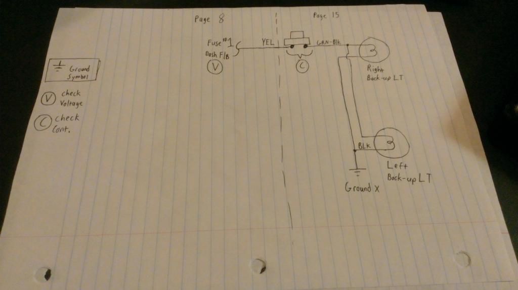 This took two pages. Page 8 and Page 15. Luckily, this is one of the more simple circuits. It consists of a fuse, switch, load (lights) and ground. I was able to simplify this circuit because I knew that fuse #1 was the source for voltage to the switch. It would have been pointless to continue tracing circuits out from this point.
Step 5: Diagnose. All of the elements are laid out. Now it's time to check them. I have symbols where you should check for voltage and continuity. You want to see if fuse #1 is good by checking for 12v on one side of back-up light switch. With the car off and in any other gear but reverse, check for continuity between the two wires (YEL and GRN-BLK). There should be non. If there is continuity, the switch may need adjustment or replacement. This is the only thing besides wires that can fail in this circuit.
Step 6: Replace/repair. Will update this when Cb7_Qc finds the problem.
/end
Dislaimer: I am not responsible for any harm or damage done to self, property, or others. 12v systems are low voltage and it is very unlikely that you will get electrocuted. These systems have high current capability. You can easily set things on fire. Be especially careful near the airbag. It is easy to deploy. It could break your face...We don't want to see a thread in the OT section about you breaking your face..
Note: this will probably be edited several times along with many addendum's. Electrical diagnostics is NOT EASY!! It's a learned skill just like anything else. It won't happen in a day.
- Tools/equipment:
You will need a multimeter. It doesn't have to be expensive since you are only using it for two things: Checking voltage and checking continuity. We shall use this 5 dollar meter for this guide: http://www.harborfreight.com/7-funct...ter-98025.html
You will also need the wiring diagrams located here:
http://www.cb7tuner.com/vbb/showthread.php?t=184559
- How to use a multimeter:
Checking voltages:
To check for DC voltages you would have the pointer in the DCV range on 20. Again, we are working with a 12v automotive system so this range is perfect. When talking about the "range" of a digital multimeter (DMM), we are referring to the placement of the decimal point.
The numbers on the DMM represent the MAX voltage it will read on that setting. The closer you are to the MAX voltage range the more accurate your readings.
Next you insert the black probe into "COM" and the red probe into 'VOhmmA.' The Greek letter Omega is the symbol for Ohms in electrical terms and means resistance. That shall be described in more detail later. DO NOT USE 10ADC!! This is for measuring current. We don't want that now. (If you want, I can describe what that does if it is requested, but for now don't use it.)
Black probe is usually tied to "chassis ground." IOW, it's touching some metal on the car. I like to use alligator clips so I can have a free hand that doesn't have to hold the probe to the chassis. From there, we can use the red probe to check voltages on wires and harnesses. This is the most common setup but there are some occasions where the black probe will have another location.
To check continuity:
Continuity is the setting we choose when we want to check if a wire is connected, broken or shorted. It checks for a "continuous" circuit. For example, a continuous circuit would be a good fuse. If we connect a AA battery to it, it would pass current. An open fuse has no continuity, no current would flow through that open fuse.
Set the meter to the ->|- symbol. This is a schematic symbol for a diode, but it is also good for checking continuity. It usually makes a sound when something has continuity so we don't have to keep looking back at our meter to see if something has continuity or not. We can check continuity with the ohms range as well, but it is silent so we would have to look at our DMM. Personally, that's too much head turning so let's stick with the diode check mode.
Placement of the black and red probe varies...With that being said, our goal using continuity checking is to figure out if something is connected or not.
DO NOT CHECK CONTINUITY WHEN YOU HAVE VOLTAGE BETWEEN TWO POINTS! This won't hurt any in our low voltage system, but don't do it. It's bad practice and it may give incorrect readings. Check for voltage first then switch to continuity and check for that if you are unsure.
- How to read a wiring diagram:
If I haven't lost you yet, good! This is probably the most important part of diagnosing electrical issues. Reading the wiring diagram. It is the road map. Without it, we would be poking at random wires with no clue where they go. Dots indicate a connection.
Brackets indicate a set of wires that are connected to another diagram.
Squiggly lines indicate one wire that is connected to another diagram
The labeling is done pretty well in the schematic.
I'm going to try to make this as concise as possible:
Step 1: Figure out what circuit your issue is on. Ex. Fan, Brake Light, Horn, etc.
Step 2: Locate the page that the circuit is on. Simple enough.
Step 3: Find your problematic circuit element.
Step 4: Trace your wiring and draw it on a separate sheet of paper. ****This is important****
Step 5: Proceed to diagnose. You should have all of the circuit elements written down. Now we have to check each individual one and the wires between them to narrow the problem down.
Step 6: Replace/repair. Once you find the problem, fix it! and you're done...hopefully. Somethings may require multiple circuits to be drawn.
That's it! Now we need an example to put everything into perspective:
http://www.cb7tuner.com/vbb/showthread.php?p=3203755
Simple reverse light issue. So we start with step 1: Reverse light circuit.
Step 2: Find the page
Back-Up LT SW C58
http://i1179.photobucket.com/albums/...ctrical-15.jpg
Step 3: Find the problematic circuit element. There may be more than one. Here we have the Back-Up LT SW and associated elements.
Step 4: Draw the circuit.
This took two pages. Page 8 and Page 15. Luckily, this is one of the more simple circuits. It consists of a fuse, switch, load (lights) and ground. I was able to simplify this circuit because I knew that fuse #1 was the source for voltage to the switch. It would have been pointless to continue tracing circuits out from this point.Step 5: Diagnose. All of the elements are laid out. Now it's time to check them. I have symbols where you should check for voltage and continuity. You want to see if fuse #1 is good by checking for 12v on one side of back-up light switch. With the car off and in any other gear but reverse, check for continuity between the two wires (YEL and GRN-BLK). There should be non. If there is continuity, the switch may need adjustment or replacement. This is the only thing besides wires that can fail in this circuit.
Step 6: Replace/repair. Will update this when Cb7_Qc finds the problem.
/end
