
Greetings all electrical wizzes and drag racers. I'm not 100% sure this is the best place for this thread, but since I have questions on an electrical install, I figure I should try here first.
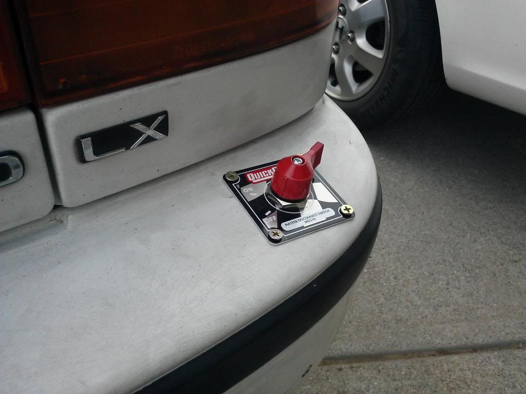
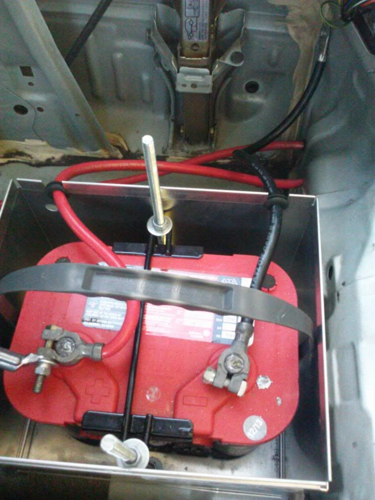
I race at an NHRA sanctioned drag strip, and I have relocated my battery to the trunk. So by NHRA regulations, I have to install a battery disconnect switch in series with the positive cable to the starter, in order to kill the motor in case of an accident. I have done so, with a four post switch: two posts for the battery and ignition, and two smaller posts for the charging circuit (alternator) which are currently not being used.
I originally purchased a 4 post switch over a 2 post switch, because one product review stated that you must use the smaller two posts in series with the alternator in order to kill the motor. Now, I am trying to figure out if I must interrupt the charging circuit with this switch as well, in order to kill the motor.
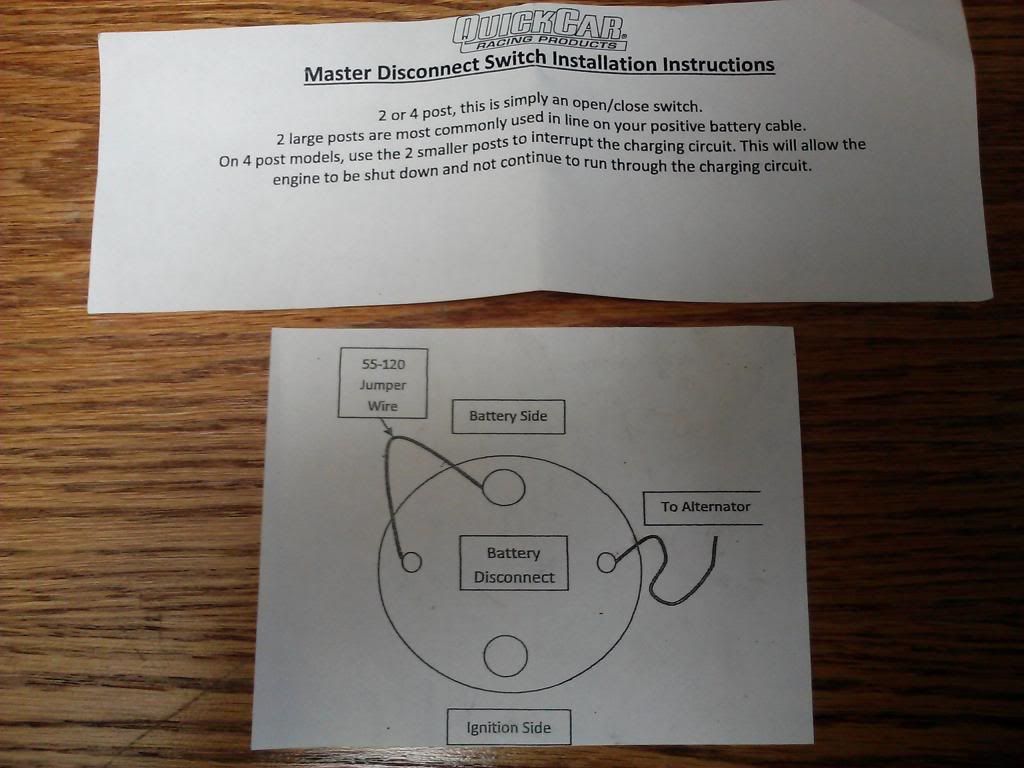
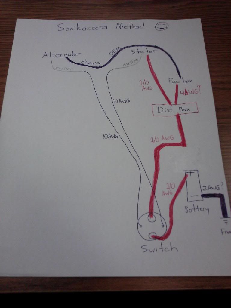
I have talked to a few mechanics and a tech official from the track since purchasing my switch, and I am getting mixed opinions. Some say, "why would you need to splice into the charging circuit when all the electric power comes from the battery?", while someone else says "yes, interrupting the charging circuit is the right way to do it, you need to create a loop of 14 gauge cable from the switch to the alternator, splicing into the exciter wire ." I also got a simplified diagram with my product, which gives yet another way to wire up all four posts:
The only testing I currently feel comfortable doing is flipping the switch when the car is off. In the "off" position, the car will not start, but the interior electrical components work (as they should, since I am not using a distribution box but sending a 4 gauge cable all the way from the positive terminal to the fuse box). In the "on" position, the car starts and everything electrical works.
Knowing all of this (sorry, I know I write a lot), do you all have any suggestions in favor or against hooking up the alternator/charging circuit to this switch? Your help is very much appreciated !
!
I race at an NHRA sanctioned drag strip, and I have relocated my battery to the trunk. So by NHRA regulations, I have to install a battery disconnect switch in series with the positive cable to the starter, in order to kill the motor in case of an accident. I have done so, with a four post switch: two posts for the battery and ignition, and two smaller posts for the charging circuit (alternator) which are currently not being used.
I originally purchased a 4 post switch over a 2 post switch, because one product review stated that you must use the smaller two posts in series with the alternator in order to kill the motor. Now, I am trying to figure out if I must interrupt the charging circuit with this switch as well, in order to kill the motor.
I have talked to a few mechanics and a tech official from the track since purchasing my switch, and I am getting mixed opinions. Some say, "why would you need to splice into the charging circuit when all the electric power comes from the battery?", while someone else says "yes, interrupting the charging circuit is the right way to do it, you need to create a loop of 14 gauge cable from the switch to the alternator, splicing into the exciter wire
." I also got a simplified diagram with my product, which gives yet another way to wire up all four posts:The only testing I currently feel comfortable doing is flipping the switch when the car is off. In the "off" position, the car will not start, but the interior electrical components work (as they should, since I am not using a distribution box but sending a 4 gauge cable all the way from the positive terminal to the fuse box). In the "on" position, the car starts and everything electrical works.
Knowing all of this (sorry, I know I write a lot), do you all have any suggestions in favor or against hooking up the alternator/charging circuit to this switch? Your help is very much appreciated
!


 !
!

 uuuugh!
Comment