
first DIY. simple enough so here you go.
so get your goodies
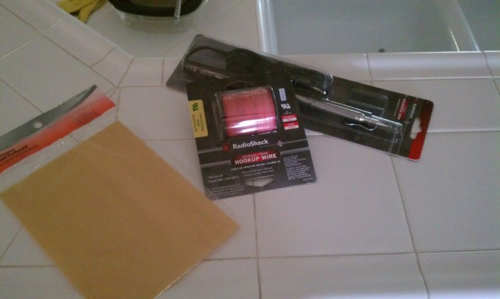
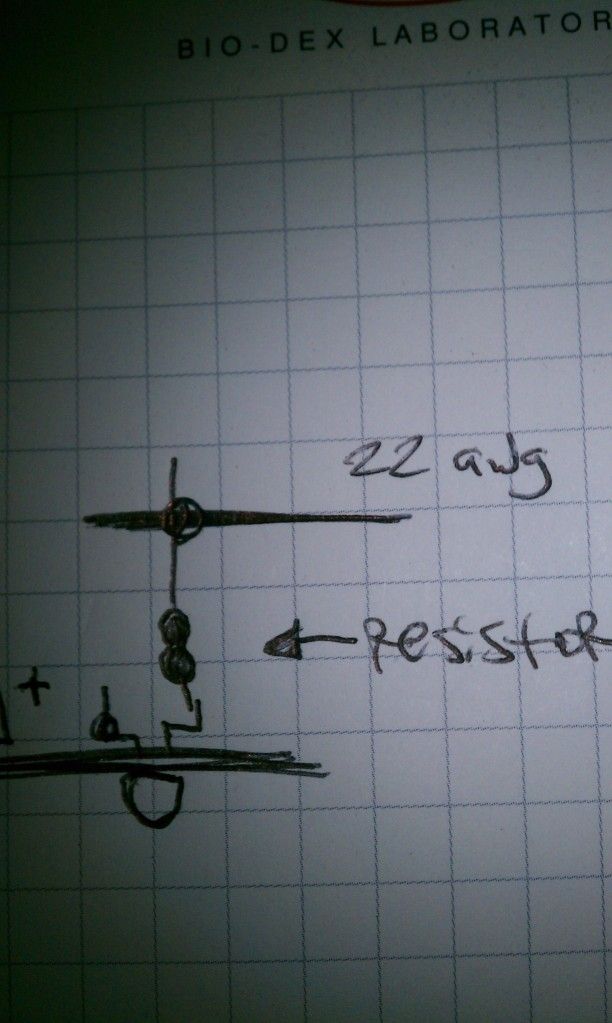
just some perf board i used 22awg wiring and the cheapest soldering iron they had at radioshack. like $6 i think. got evrything there except the leds and resistors.
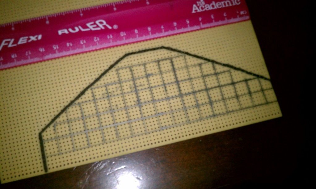
i shaped mine out to fit into the housing and use the reflector because i didnt want to see the bright circles of the individual leds through the lens.
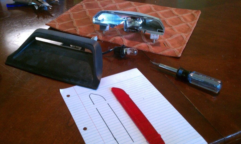
but if you want to do it like that and use less leds then you can shape out your board to hold the leds facing towards the lens more like this
i used theese leds from superbrightleds.com

8mm led 360 degree beam continuous forward current of 60mA (milli amps)
and i paired them with 1 watt 5% 220 ohm resistors from circuitspecialists.com best assortment for resistors i found excellent selection
so i cut out the perf board to my shape. and stripped bare 2 lengths of the 22 awg wire.
find a good starting point and line up the leds. orientation of the bulb should be the same. as in postive ends all on the same side lined up in rows.
after the led is on the board, using some needle nose pliers i bent the base of the wires that were fed through the holes on the perf board on the bulb just a bit. that way it keeps the leds in place on the board.
do this for all of them. then your ready to solder. its easier to connect all the negative up first. i kind of wove my wire through all the negative leads row at a time. then solder up each connection. bend the 22 awg wire at the end of the row and line it up for the next row of negative leads and do the same thing. repeat until done. then clip all the excess negative leads from the leds.
now you might want to put electrical tape over the negative wiring and soldering. i didnt do this but i should have. just because you dont want positive touching negative and somce the fittment is going to be tight in the housing and you want as much room as you can get.
next clip off part of the positive leads on the bulbs. and also clip part of one side of the resistors you will need. solder up your resistors to the positive leads(both short ends).
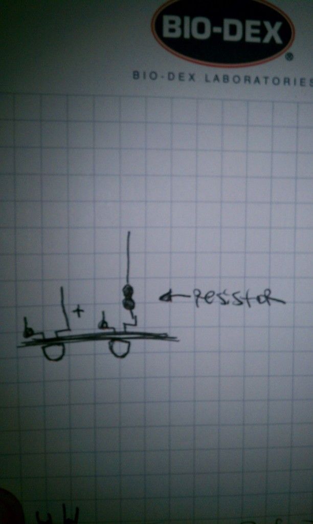
get your second length of stripped 22 awg wire. and do the same thing you did before. but weve it through the resistor lead. once those are soldered up you can clip the excess resistor leads. it might help if you wrap the resistor lead around the 22 awg wire then soldering it.
once they all soldered up carefully push down the positve stuff. basicly laying it down.
and push the end of the 22 awg wire to be connected to the bulb socket through the perf board to anchor it in place before soldering to bulb socket.
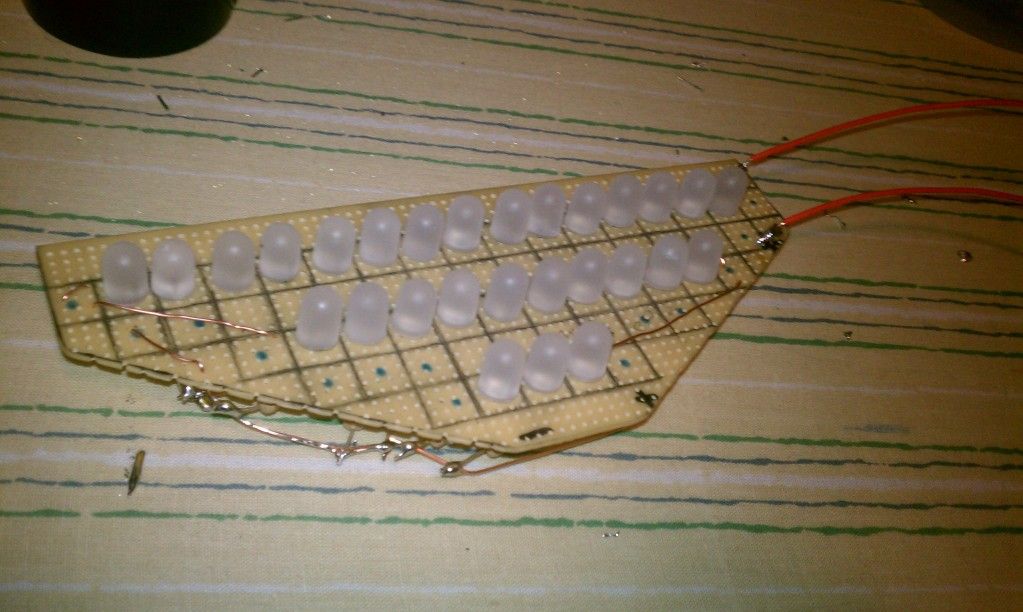
the bulb side of mine
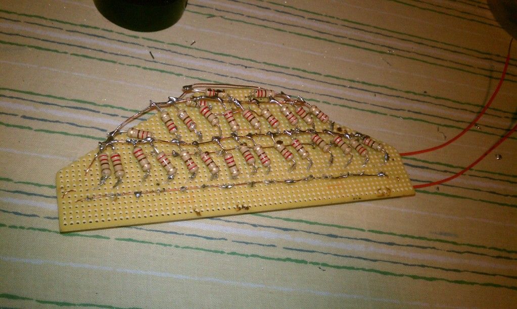
and the underside with all the wiring
get an 1156 bulb and wrap it in a paper towel or rag. and break the globe with a hammer. connect it to the 3rd brake light socket. be careful for sharp edges and have someone apply the brakes and you figure out which side is positive and which is negative by touching the wires of the new led brake light to the wires on the socket. remember which ones which on the socket. and take it back out. again being careful solder them up like so.
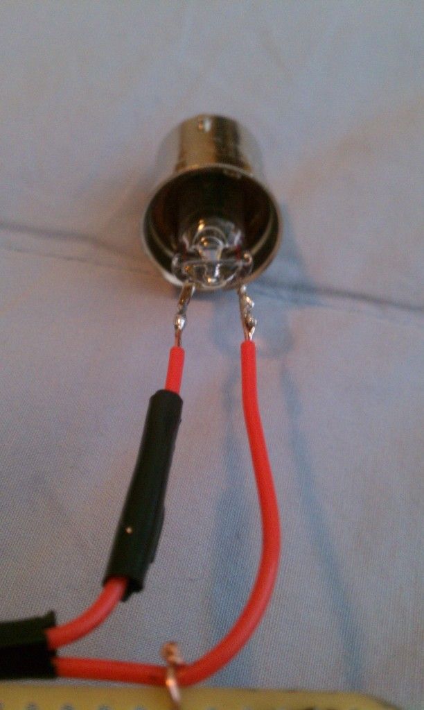
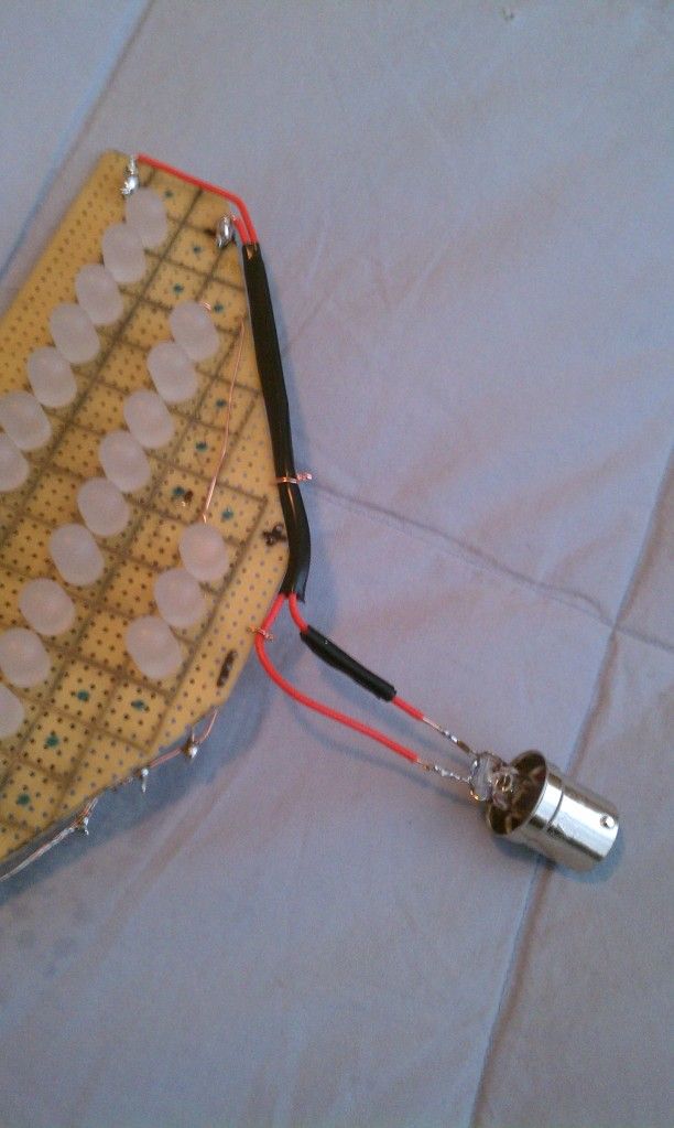
what i did at the end there was twist the bare wire i had that was hooked up to the lights with a new piece of unstripped wire and soldered a fat bead on there. did that for both positive and negative wires. and then cleaned it up with some electrical tape and tied it in place with bare wire.
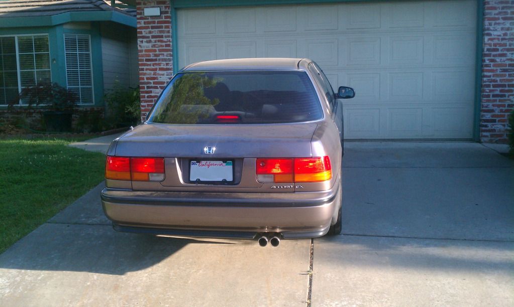
put it in the housing and connect your socket into the socket thingy test again to make sure its all good and if it is your basicly done. just re assemble 3rd brake light housing and rear deck.
heres mine in my room
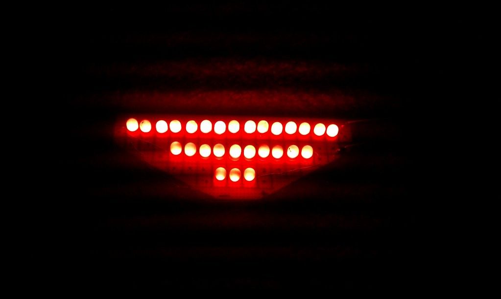
taken during the day. camera on my evo 4G had to black out the rest of the room to get focused shot of the leds
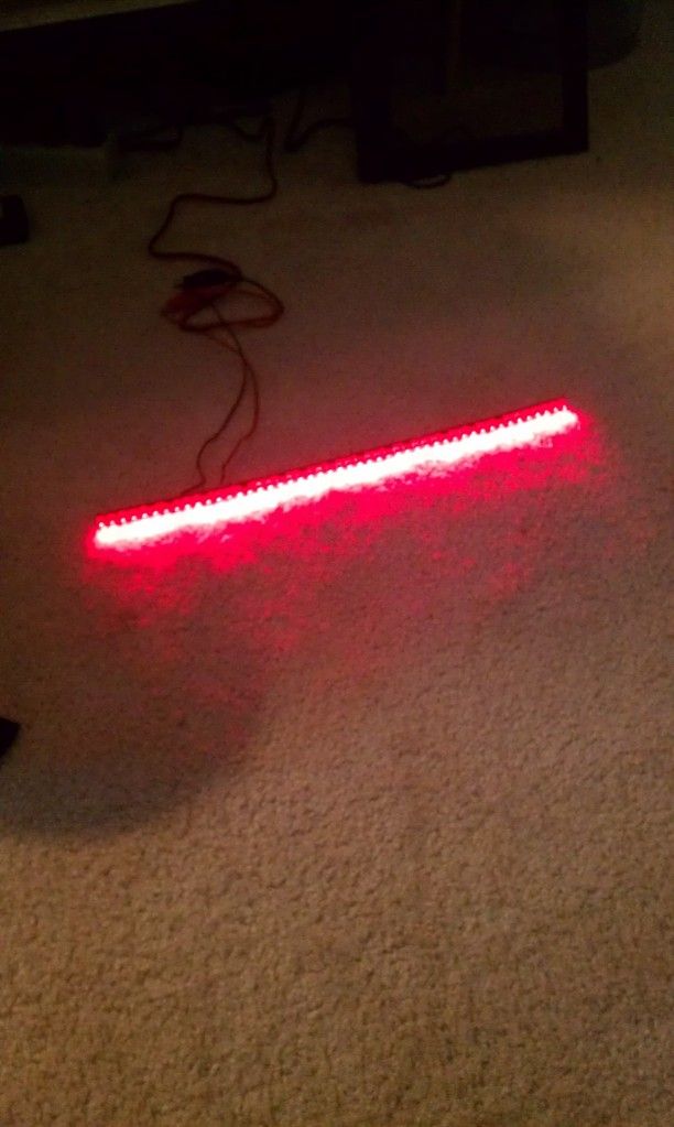
in a dark room
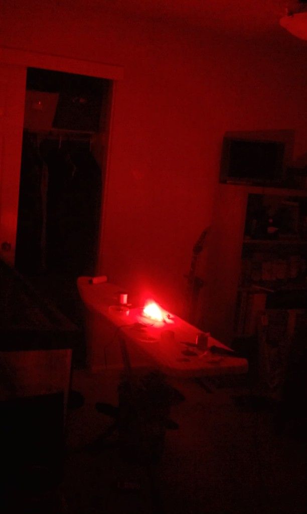
during the day 10 feet away
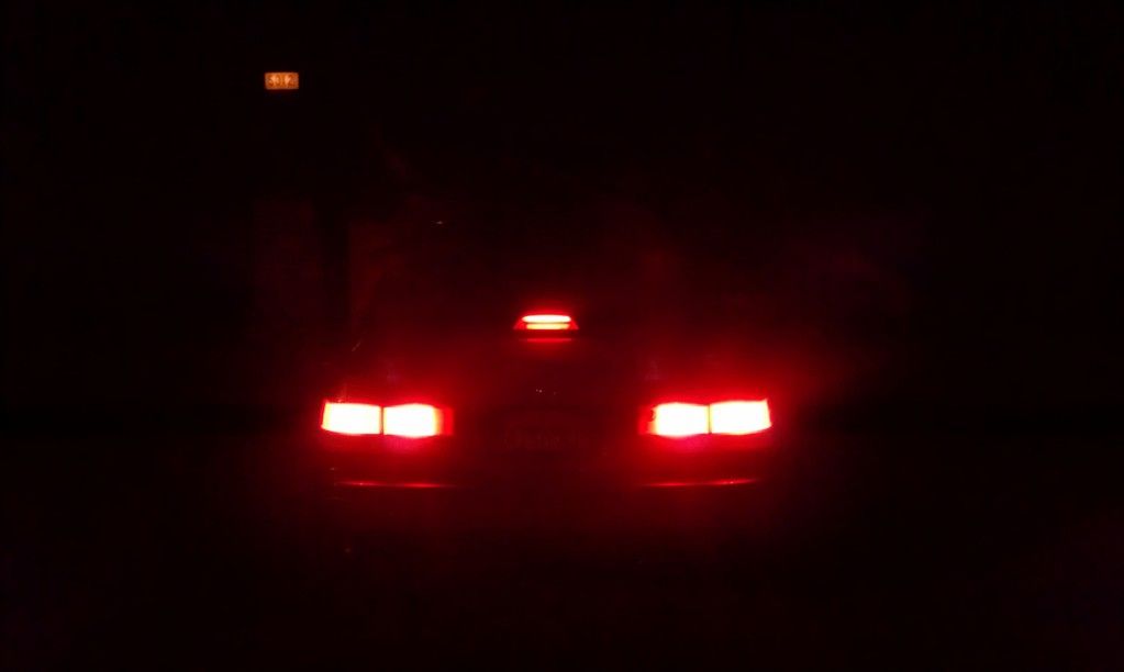
at night same distance
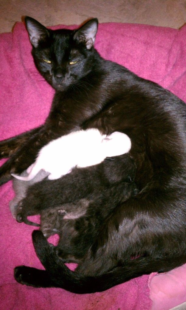
as a reward a random picture of kevin and her kittens
anyone want a DIY on rear deck removal? i know there isnt one. but it took me a while to figure it out.
so get your goodies
just some perf board i used 22awg wiring and the cheapest soldering iron they had at radioshack. like $6 i think. got evrything there except the leds and resistors.
i shaped mine out to fit into the housing and use the reflector because i didnt want to see the bright circles of the individual leds through the lens.
but if you want to do it like that and use less leds then you can shape out your board to hold the leds facing towards the lens more like this
i used theese leds from superbrightleds.com
8mm led 360 degree beam continuous forward current of 60mA (milli amps)
and i paired them with 1 watt 5% 220 ohm resistors from circuitspecialists.com best assortment for resistors i found excellent selection
so i cut out the perf board to my shape. and stripped bare 2 lengths of the 22 awg wire.
find a good starting point and line up the leds. orientation of the bulb should be the same. as in postive ends all on the same side lined up in rows.
after the led is on the board, using some needle nose pliers i bent the base of the wires that were fed through the holes on the perf board on the bulb just a bit. that way it keeps the leds in place on the board.
do this for all of them. then your ready to solder. its easier to connect all the negative up first. i kind of wove my wire through all the negative leads row at a time. then solder up each connection. bend the 22 awg wire at the end of the row and line it up for the next row of negative leads and do the same thing. repeat until done. then clip all the excess negative leads from the leds.
now you might want to put electrical tape over the negative wiring and soldering. i didnt do this but i should have. just because you dont want positive touching negative and somce the fittment is going to be tight in the housing and you want as much room as you can get.
next clip off part of the positive leads on the bulbs. and also clip part of one side of the resistors you will need. solder up your resistors to the positive leads(both short ends).
get your second length of stripped 22 awg wire. and do the same thing you did before. but weve it through the resistor lead. once those are soldered up you can clip the excess resistor leads. it might help if you wrap the resistor lead around the 22 awg wire then soldering it.
once they all soldered up carefully push down the positve stuff. basicly laying it down.
and push the end of the 22 awg wire to be connected to the bulb socket through the perf board to anchor it in place before soldering to bulb socket.
the bulb side of mine
and the underside with all the wiring
get an 1156 bulb and wrap it in a paper towel or rag. and break the globe with a hammer. connect it to the 3rd brake light socket. be careful for sharp edges and have someone apply the brakes and you figure out which side is positive and which is negative by touching the wires of the new led brake light to the wires on the socket. remember which ones which on the socket. and take it back out. again being careful solder them up like so.
what i did at the end there was twist the bare wire i had that was hooked up to the lights with a new piece of unstripped wire and soldered a fat bead on there. did that for both positive and negative wires. and then cleaned it up with some electrical tape and tied it in place with bare wire.
put it in the housing and connect your socket into the socket thingy test again to make sure its all good and if it is your basicly done. just re assemble 3rd brake light housing and rear deck.
heres mine in my room
taken during the day. camera on my evo 4G had to black out the rest of the room to get focused shot of the leds
in a dark room
during the day 10 feet away
at night same distance
as a reward a random picture of kevin and her kittens
anyone want a DIY on rear deck removal? i know there isnt one. but it took me a while to figure it out.

Comment