Announcement

Collapse
No announcement yet.

SSMAccord : 1992 Accord EX

Collapse
X
 
  • Filter
  • Time
  • Show
Clear All
new posts

    Originally posted by SSMAccord View Post

    My shifter was part of a group buy at some point, probably 2005 or so. The shift boot wasn't too short, but it would be taut in certain gear position. The original P Spec boot eventually wore out, I used it as a template to make a replacement boot. I did add an extra 1-1.5 inches to the pattern to allow more play in the shift boot overall.

    Thanks man!

    Mine is still OK. Not stellar, but not bad. It just irritates me that the back side is about 1.5" too short, so it pulls free and comes out. Only way to fix it is to take the whole console apart again. I was considering doing what you did, but I also may just buy something like a Type-R boot.

    I really appreciate the response!
    The OFFICIAL how to add me to your ignore list thread!

    Comment


      I managed to get the brake set up completed just in time to do a very late night oil change and a mechanical once over of the car before having to head off to a weekend of camping and a track day at Gingerman Raceway in west Michigan. The event was hosted by AutoInterests and is currently the only organization that runs the Gingerman course in reverse traffic direction. I had not previously run with this organization or in this configuration of the track, but I was eager to kick off track events for the season.

      FT Inspection Label


      The day started with a few more last minute checks on the car; I discovered that one of the rear sway bar mounting bolts was loose, so I set about tightening that up before the driver's meeting and first classroom session of the day. During the travel to the track, I encountered a Code 21 that caused the car not have valve lift functionality, I did some troubleshooting but was not able to resolve the issue and decided to deal with that after the event.

      Morning Check In


      The AutoInterest event was really well done; they pair you up with a dedicated instructor, have really informative classroom sessions, they also have vehicle dynamic sessions in between the on track sessions that keeps the fun going throughout the day. They also do a track walk which is really useful for learning more about the track surface and some of the more intricate details for navigating certain turns and sectors. I really enjoyed the event overall and look forward to running more events with this group.

      Track Walk


      Before the first on track session for my group, there was a vehicle dynamics sessions that was a good warm up before heading on to a hot track. After that task, I decided to check the vehicle just before going out on track and discovered one of the small hoses that feeds between the thermostat and the IACV had split and sprung a leak. Fixing it by cutting the end was simple enough, just inconvenient. Other than the consistent Code 21, the day was pretty uneventful mechanically. I did decide that as my last track session of the day wrapped up, the front wheel bearings might need to be replaced; they likely suffered premature wear from being overheated last year. The brakes themselves seemed to perform as anticipated, the color grading indicated that the rotor faces got pretty warm but the rotor hat areas stayed cool, which was the intent. The pedal is firm and the amount of brake pedal travel needed has decreased which led to a modification of my heel/toe technique due to the relative height of the brake pedal versus the accelerator pedal.

      Vehicle Dynamics Session


      Post Track Brake Check


      Cool Down between Sessions


      The track itself was really fun in reverse configuration and the variety of cars at the event was quite good. I found myself really digging a patchwork-y Fox body Mustang that was in the advanced group amongst other cars. Casey's ND Miata was also doing really well on track, riding along with him is always really informative. There were also a few WTAC and GLTC cars in attendance as well.

      Track Photos from NVUS Images


      http://www.hondanews.com/releases/19...d-introduction

      Comment


        That looks like so much fun. That stinks about the code 21 and not letting you go into vtec. But glad to hear your brake issue was resolved. I need to go to a track one day and see how my car performs. But I will lower the boost to something that won’t crack the wheels loose every time I give it a decent amount of gas.

        how do you have your feet positioned for your heel toe? I could never find a good positioning that allowed me to effectively use the technique.
        ~Nick~
        FSAE (F Series Accord Enthusiasts) ..."A dying breed thats taking it to the next level" Lucky #13
        MR Thread:http://www.cb7tuner.com/vbb/showthre...ight=Grumpys93

        Comment


          That's awesome! Getting to any track has traditionally been difficult for me since there were none anywhere near me. Hopefully, I'll get to try it out here someday just to see how it is setup.

          I assume you are running a 1" master cylinder on this brake setup? I am trying figure out exactly which cars have them (I thought all VTEC Preludes did, but that may not be correct). I will also have to adapt mine since I have a 15/16's and the one of the fittings is apparently different. I think the ABS Accords came with a 1" standard didn't they?

          I also followed your lead and ordered the Honed Performance rear spindle nuts. They should be here shortly after they finish clearing Customs, which is where they are now.
          The OFFICIAL how to add me to your ignore list thread!

          Comment


            Originally posted by Grumpys93 View Post
            That looks like so much fun. That stinks about the code 21 and not letting you go into vtec. But glad to hear your brake issue was resolved. I need to go to a track one day and see how my car performs. But I will lower the boost to something that won’t crack the wheels loose every time I give it a decent amount of gas.

            how do you have your feet positioned for your heel toe? I could never find a good positioning that allowed me to effectively use the technique.
            It is really fun. It is also really informative about how your behaves and identifying deficiencies in the car and personal driving skills lol. I do have a great time, but it can be tiring after like the 5th or 6th session of the day. Usually by 4 I’m too exhausted to participate in the free track/all groups track time.


            I think you’d have a blast a track day! Too much power and not enough grip can be an issue on track, but you may find that leaving alone initially might be ok. There are actually less moments of full throttle usage on track. It’s mostly trying to manage car placement, balancing available grip and focusin@ weight transfer as you set up for the next turn/sequence.

            I did a bunch of troubleshooting after the event, it seems like the ecu might be the culprit as everything else meets the criteria in the service manual troubleshooting guide.

            My heel/toe technique is very influenced by the Best Motoring videos lol. Pressing the brakes with the ball of the foot and rotating the heel out to blip throttle, it also requires more throttle that you’d think for a good ‘blip’. The maneuver got slightly more difficult after installing braided brake lines since there was less brake travel needed for adequate braking which left my heel kind far from the throttle when heel/toeing. The new brake setup needs even less travel, getting the brake pedal far enough down to contact the throttle puts the car into panic level braking. I think the solution is a pedal cover that is spaced to make the relationship between the throttle and brake closer.
            http://www.hondanews.com/releases/19...d-introduction

            Comment


              Originally posted by owequitit View Post
              That's awesome! Getting to any track has traditionally been difficult for me since there were none anywhere near me. Hopefully, I'll get to try it out here someday just to see how it is setup.

              I assume you are running a 1" master cylinder on this brake setup? I am trying figure out exactly which cars have them (I thought all VTEC Preludes did, but that may not be correct). I will also have to adapt mine since I have a 15/16's and the one of the fittings is apparently different. I think the ABS Accords came with a 1" standard didn't they?

              I also followed your lead and ordered the Honed Performance rear spindle nuts. They should be here shortly after they finish clearing Customs, which is where they are now.
              Yeah, this car had the 1” stock, but my old 91 used a modified hose to install the 1” master cylinder.. I think all Si and Si Vtec Preludes do have 1” units.

              Good choice on the axle nuts! I’m glad that they aren’t backordered for the time being.
              http://www.hondanews.com/releases/19...d-introduction

              Comment


                Originally posted by SSMAccord View Post

                Yeah, this car had the 1” stock, but my old 91 used a modified hose to install the 1” master cylinder.. I think all Si and Si Vtec Preludes do have 1” units.

                Good choice on the axle nuts! I’m glad that they aren’t backordered for the time being.
                Thanks for the input. Perhaps I can just order one from an ABS CB7, since I believe those are 1". I have a master cylinder from a Prelude (it was supposed to be a VTEC), but it is only 15/16, so I think it must have come from a "base" model. I bought it on ebay years ago, so I'll just have to chalk it up as lesson learned. The hardest part will probably be figuring out the adapter, but that should be doable. If nothing else, I'll buy the stuff to do it since it would be nice to have those tools anyway. Any excuse to buy tools! LOL.

                Yeah, I was happy they were available too! One of the reasons I didn't wait was that I think I got the last set they had in stock!

                I was curious if wheel lock was an issue in a track setting. Having brakes that powerful without any sort of ABS intervention makes it seem like that they would lock really easily. I know it is a fairly common setup these days, but still.

                Other than that, how was the car's overall setup? Do you need to tweak some stuff, or is it pretty good out of the box?
                The OFFICIAL how to add me to your ignore list thread!

                Comment


                  Originally posted by owequitit View Post

                  Thanks for the input. Perhaps I can just order one from an ABS CB7, since I believe those are 1". I have a master cylinder from a Prelude (it was supposed to be a VTEC), but it is only 15/16, so I think it must have come from a "base" model. I bought it on ebay years ago, so I'll just have to chalk it up as lesson learned. The hardest part will probably be figuring out the adapter, but that should be doable. If nothing else, I'll buy the stuff to do it since it would be nice to have those tools anyway. Any excuse to buy tools! LOL.

                  Yeah, I was happy they were available too! One of the reasons I didn't wait was that I think I got the last set they had in stock!

                  I was curious if wheel lock was an issue in a track setting. Having brakes that powerful without any sort of ABS intervention makes it seem like that they would lock really easily. I know it is a fairly common setup these days, but still.

                  Other than that, how was the car's overall setup? Do you need to tweak some stuff, or is it pretty good out of the box?
                  You probably do have a MC from a Prelude S, Si and Si VTEC have the 1" MC. You can actually just carefully cut the flare off of your existing brake hose, the one closest to the firewall if my memory is working, and remove the old fitting and put on the correct fitting and reflare the hose. It is a tight fit for the flaring tool because of the bend in the hose, but it can be done. (you also only get one chance because the hose will be too short if you screw up the flare and have to attempt it twice.)

                  Wheel lock is generally not an issue on track unless the surface is compromised from moisture, dirt/debris that someone has brought on track or automotive fluids. Wheel lock is very dependent on tire friction; sticky 200TW tires require a lot of force to lock once they are heated up, pedal modulation is key and having wider range of braking torque available allows for more precision in the amount of braking being applied.

                  I have found during the pad bedding process that the rear brakes do tend to lock up before the front brakes, this is likely a common occurrence as people tend to refer to that kind of scenario as an indication of brake proportioning. It actually is due to weight transfer; when the car is in "daily driving" mode I turn the dampers adjustment to full soft front and rear which allows for very abrupt weight transfer to the front in panic/brake bedding levels of brake engagement which causes the rear brakes to lock up because the rear wheels are suddenly carrying less weight. This would also be very likely to happen on a stock or worn suspension setup. On track the dampers are set to be much more firm to slow the weight transfer to the front of the car which allows the rear to maintain traction and avoid locking the rear brakes.

                  The car feels ok on track, I have not fully dialed in the alignment yet. I intentionally have it set up to be "safer" and rely on understeer at the limit instead of trying to coax the rear to rotate. Once I get a better alignment setup, I will probably try to dial in more rear rotation. It is very clear that the car is quite heavy compared to EK hatches, newer Civic Si's and Miatas and the longish wheelbase keeps the car from being overly nimble with the benefit being that it is more stable.

                  To that end, one of the last backordered parts, Hard Race roll center adjusters finally arrived. These would have had an effect on the demeanor of the front end and how the weight transfers laterally. I had a machine shop replace the wheel bearings and I installed the RCAs with balljoint kit. Hopefully most of the suspension setup is ok for a while. The old wheel bearings were allowing a bit of play as I noticed when disassembling the front end, the previous overheating must have really caused them to start to fail prematurely. The old bearings were also not OEM parts which might also be a factor.


                  Wheel Bearings


                  Roll Center Adjusters


                  Roll Center Adjusters Installed
                  http://www.hondanews.com/releases/19...d-introduction

                  Comment


                    2022ish... CB update. I hadn't planned to do much of anything to the CB during the winter downtime and into 2023. I did want to solve the car losing its VTEC functionality and indicating Code 21 which plagued me the entirety of 2022.
                    Late in 2022 I decided that none of the things I had tried resolved the Code 21 issue. I went through checking for continuity in the wiring, checking for VTEC solenoid operation, checking for broken ECU pins, leaky capacitors and bad grounds to no avail. Not having a back-up ECU I decided to acquire a stock P13 ECU to see if that would solve the issue.


                    The first thing that happened is that the P13 threw a few error codes: EGR operation and Knock Sensor in addition to driving like absolute crap. The knock sensor wire was disconnected because the knock sensor itself had been damaged previously. The chipped ecu didn't need if for operation so I never bothered to fix that until this incident warranted it. Given the nature of this problem solving method, I went with an non OEM knock sensor from Rock Auto. After some creative wrenching the old broken sensor was removed and the new sensor installed.


                    That repair complete, I checked the EGR for issues and found none, ditto for the wiring as well. Turns out the vacuum hose was split and not allowing the system to function. With all of the repairs made it was time to find out what results this combination of parts would yield. Firstly, the car drove like normal which was a relief and no codes were being indicated. I cautiously approached lift threshold expecting to get Code 21. To my surprise the car engaged lift with no codes indicated, yay. At least for a while, after about 10 minutes the car would indicate Code 23 for the knock sensor which I figured would happen with a cheapo part. Not a huge deal, at least I was able to single out the chipped ECU as the likely culprit for my VTEC woes.


                    The problem of the car leaking a small amount of coolant when the heater valve was opened had also reared its ugly head again. Having already replaced the heater valve in 2021, it seemed like the issue was that the heater core was blocked and leaking out of the hose. It seemed odd because I still had heat from the vents...I figured that I would reverse flush the heater core in the spring and try to remove the blockage and alleviate the issue.


                    For a simple winter project I was planning to replace the 3M PPF that was used on the taillamps and wheel center caps. I thought that it was just the passenger taillamp being affected by exhaust gas, but as I started to notice all of the taillamps were yellow and the PPF on the wheel center caps was also prematurely yellowing. I use PPF on the taillamps to protect the painted part as it is quite fragile, the wheel caps are PPF'd to keep the metal part of the cap attached to the plastic cap, these tend to fail and go missing as the adhesive pads loose their adhesion. The PPF is only 2.5 years old which is kinda odd for it to be so yellow. The internet searches indicated that the film likely was not yellow, but the adhesive may have been the actual culprit. Anyhow, it needed to be replaced and can easily be done indoors. I decided to change PPF brands to XPEL in the hopes that it will not yellow a prematurely.


                    This was the state of the PPF on the taillamps and wheel caps. The left cap is the old PPF.
                    http://www.hondanews.com/releases/19...d-introduction

                    Comment


                      I had been eyeing a modified cylinder head for a longish period of time but A: those are cost prohibitive and B: I didn't want to modify my Euro-R head. Somehow the stars aligned in 2022; in the spring a BB6 Prelude arrived at one of the local salvage yards. Knowing that those cars are usually picked over after about 48 hours on the yard, I figured it would be a husk. To my surprise the only things missing were the intake (probably an aftermarket part) and the front seats when I managed time to get to the salvage yard, under the hood was a blue top H. The engine had the stamped steel oil pan versus the cast aluminum oil pan a BB6 Prelude should have and no way of knowing if this is the 180hp auto version or the 197hp manual version, but the car clearly had an engine replacement at some point. The price of any cylinder head at this yard is $60 so I couldn't pass up the chance to get a spare P13 cylinder head.

                      Salvage Cylinder Head


                      In the fall, 4 Piston Racing had a black friday promotion going that would save a nominal amount of money off of their modified cylinder heads. Having the spare cylinder head I placed an order and sent the head off to be serviced just before the Christmas holiday hoping that I had properly packaged the head for safe delivery.


                      In the mean time I needed to begin assembling the upgrade and performance items that would need to be addressed for this project. To start one of my goals was to increase the compression ratio of the engine to make better use of aftermarket cams without needing to get into sleeving the block or custom internals. Using the internet and a couple of popular compression ratio calculators it seemed to be that removing .027 from the head would bump the Euro-R compression from 11:1 to somewhere around 11.7:1, not a full point of compression but a decent bump. (The calculator spits out 10.8:1 as the stock Euro-R comp. ratio while it should be 11.0:1 according to Honda data, so the compression ratio would be 11.7:1 using that method) I decided to spec the head to be shaved .015 to accomplish roughly half of that and ordered 3 variations of Cometic headgaskets in .018, .027 and .030. Using the .018 gasket would get me to my intended compression bump.


                      Headgaskets


                      Zeal Chart


                      I also needed to address the ECU issue and also intended to have a Hondata S300 setup installed to be able to tune the new engine setup. Given that the existing ecu was from Phearable and had served me well up until this recent issue, I decided to send the ECU back to them to troubleshoot the VTEC issue and install an S300 system. That was process was pretty easy, in their troubleshooting they couldn't find any issue with the ECU operation which was curious...I still had them replace the capacitors during the S300 install for good measure. I also ordered a CPR kit to complete the setup and upload a 'premium' base tune to at least get the car running when the time came.

                      Hondata Goods


                      Given the recreational nature of the CB these days I decided that a few parts would need to be replaced or upgraded in addition to any maintenance that needed to be done. Skunk 2 Pro2 Cams and their adjustable cam gears would replace the stock parts. ARP headstuds would replace the OEM bolts and also hold the thinner head gasket in compression instead of tension like the OEM parts which hopefully prevent any leakage there. ARP bolts would also be used on the flywheel and clutch when we I went to reinstall those parts.

                      Internal Bits


                      Fast forward a few months to March and a rather large and heavy box is being delivered to my porch. Given the goings on at my house in the spring it could have been bulk paper towels, but it turned out to be a box from 4P. Inside was my modified cylinder head and all of my rocker assemblies and VTEC pins randomly in a plastic bag. I probably should have disassembled them before I sent it away to keep them mated the way that the service manual specifies, but I didn't know that would be the case. The head is CNC ported and equipped with Supertech valvetrain components and Ferrea valves. The valve guides, valve locks and valve seals were all replaced as part of the process as well.


                      4P Cylinder Head


                      Given the amount of work needed and other maintenance items I needed to address, it was decided to take the engine out of the car. The process was about like I remembered it, tedious. Especially considering I couldn't get the passenger side driveshaft out of the trans the last time I needed to service it and ended up having to tap the driveshaft out from the intermediate shaft input side of the trans. Getting the engine mounted to the engine stand was a challenge too; the last time I had the engine out in 2017 I failed to successfully get it on the stand, but I proved to be able to do so this time which would make the workflow of replacing parts and blueprinting the head much easier.


                      Engine on Stand


                      With the engine on the stand it was clear that my small oil leak on the driver's side was from the balance shaft seal, I replaced the seal the last time that the engine was out and installed the retainer but this was just a wonky/leaky seal. I hadn't planned to remove oil pump this go round and decided to put that off until later in the process. I also noticed that the header had been leaking at the flange on a couple of cylinders and at the slip joints. Anyhow onto what I needed to do: degreeing the cams (thankfully Accord Aero-R had also shared his experience with this so I had a benchmark), calculate piston to valve clearance and valve to valve clearance. I set about getting the head removed from the block and getting the head setup for the blueprinting. Removing the head it was clear that the previous tune had been running rich, as I had suspected (the piston tops had a lot of built up carbon); it looks like the header leak had allowed air in the exhaust path and been causing the O2 sensor to compensate for the "lean" reading by adding more fuel. Which would also explain the fuel economy hit that occurred after I swapped to the 4-2-1 header the last time the engine was out.

                      Cylinder Head Removed


                      Rubberbanding and removing the rocker arm sets, I set them aside and labeled them for reinstallation later. I locked the rocker arms into the valve lift state and reassembled the arms into the #1 cylinder and then reinstalled the rocker shafts and bottomed out the valve lash. Given the intent to bump the compression via the head shaving and the thinner headgasket, I would be approximating the final setup dimensions by gently bolting the cylinder head to the block without a headgasket to make the measurements. The stock head gasket measures .0265"and removing it from the assembly would be the equivalent of the final assembled stack up of my proposed setup. Utilizing a few internet guides and YouTube tutorials, I gathered up 2 clay options that I had from a different crafting project and set about getting the measurements for the Pro2 cams. This process would end up taking a lot longer than I anticipated...

                      Rocker Arms


                      The first task was to find true TDC using a piston stop, degree wheel/kit and a little bit of math. After a couple of attempts and getting the same results, I settled on where true TDC was and marked that off for reference.

                      Degree Kit


                      Flywheel and Cam Tool


                      Clay on the #1 piston that is set at true TDC, put the cylinder head on, snug the bolts down **not torqued**, lube/ install the cams, install cam caps, install the cam gears...then I realized that I didn't have the cam gear woodruff keys. Had I dropped them? Had I even seen them? I had not done either. Turns out 98+ H22s don't have separate woodruff keys, they are an integral part of the cam gears. Well, maybe the blue top cams would have the keys? No dice. I didn't really want to wait a week to order them from Majestic, but I could run a parts search to see if some other car used the same keys. Turns out the B20 out of a first gen CR-V would have the requisite parts and there just so happened to be one of those at the salvage yard. I got up the next day, put the tools in my car and stopped in to the salvage yard to find that some gracious human had already partially disassembled the CR-V engine which saved me a bunch of time and I still managed to make it into the office before 10am.


                      Cam Gears


                      CRV @ Salvage


                      Back on track that evening, I got the cam gears installed onto the camshafts, installed the timing belt, adjusted the cam gears to a set degree, rotated the engine 2 full rotations, disassembled, gently cut the clay in half, removed from piston, measured, jotted down the measurement for intake and exhaust, repeat. Each cycle taking about 35-40 minutes...I did this numerous times. After probably a week of this process it was complete and I had a complete P2V clearance data set. There was a very clear area on the exhaust cam that could not be utilized.


                      Clay Process


                      After that process was complete, valve to valve clearance would need to be calculated. Using a post from NZHonda as a reference, I again bolted the cylinder head to the block only this time the head is one cylinder out of position so that the #1 combustion chamber overhangs the block. Using an old timing belt and vise grip pliers, it is possible to rotate the cams to measure the clearance between the valves. The internet rule of thumb is .035" - .040" minimum clearance between the valves, I began this process with the cams set to IN @ 0 / EX @ 0. Oddly one set of valves was very close to contact while the other set of valve were well within the spec of .040...hmm, maybe that is how the cams are designed? As some cams do stagger opening and closing between lobes to minimize shock to the valve seats. I managed to get through all of the V2V clearances but the data still looked...off somehow. In addition to that oddity, I noticed that when the cams were at TDC and the valves should be closed some of the valves were not seated. After a little bit of digging, I realized I had made a giant error at the beginning of this process, I set the valve lash to .00" without the cams installed and the caps torqued in place. Essentially the rockers were just bottomed out which meant the valves had been a random heights since I had began the P2V measurements, *Scooby Doo voice* ruh roh...


                      After this revelation settled in, I set about properly setting the valve lash to .00". At least getting the V2V measurements could be done and after sometime I was able to determine that to maintain a minimum of .034" V2V the cams needed to be separated by 4 degrees at any given time. That done, it was time to go back and re-do ALL of the P2V clearances. *weeps into hands* Once I had all of this info, I could make a safe clearance chart for P2V and V2V that could be used if cam tuning would be needed in the future.

                      P2V Notepad


                      Measurements Taken

                      Last edited by SSMAccord; 10-02-2023, 12:50 AM.
                      http://www.hondanews.com/releases/19...d-introduction

                      Comment


                        Looks awesome! Are you going to paint the head at all? I imagine now...
                        Ahhhhh wow, this is what I need to do with the spare had I have. Especially since the current head makes a ton of noise and rattling. But ....... that looks confusing. But I also don't want to pay someone to do it. But I do need to learn it. ha. That last graph I don't even understand. I would assume that all valves would have the same clearance as they are all setup the same, same seats, same springs, same valves. & you are just figuring out the head gasket requirements here?
                        I still haven't saved up the $$$ for the Skunk 2 Pro cams, they are costly!

                        Comment


                          Yeah, I'm glad the assembly part's over for me, haha. Super excited to see how this turns out, given the similar specs to my build. Wish I could have afforded CNC ports, though, that head's gorgeous!

                          Accord Aero-R

                          Comment


                            Originally posted by Raf99 View Post
                            Looks awesome! Are you going to paint the head at all? I imagine now...
                            Ahhhhh wow, this is what I need to do with the spare had I have. Especially since the current head makes a ton of noise and rattling. But ....... that looks confusing. But I also don't want to pay someone to do it. But I do need to learn it. ha. That last graph I don't even understand. I would assume that all valves would have the same clearance as they are all setup the same, same seats, same springs, same valves. & you are just figuring out the head gasket requirements here?
                            I still haven't saved up the $$$ for the Skunk 2 Pro cams, they are costly!
                            I am not planning to paint the head. I did repaint brackets as they were chipped and had some rusting. I also didn't know how to do any of this, the internet has a bunch of tutorials that make it easy to do. All of the valves should have the same measurements, so you only have to do the process on one cylinder. The reason for the process is to know that the higher lift cams won't collide with the pistons and where the limits of adjustability for the cam gears are before you have a piston to valve interference.


                            Originally posted by CyborgGT View Post
                            Yeah, I'm glad the assembly part's over for me, haha. Super excited to see how this turns out, given the similar specs to my build. Wish I could have afforded CNC ports, though, that head's gorgeous!
                            Thanks, I think we are in the same dyno tuning limbo as I haven't had the car tuned yet due to some issues with the Hondata setup or something I did that I haven't figured out.

                            the story continues...
                            This part of the journey completed, it was time to tackle the easier maintenance items. I had remembered that the oil pump didn't need to be removed to service the balance shaft seal, it can be removed and seated without that bit of work. I carefully removed the seal and set the new seal in place and reinstalled the retainer. Some research suggested that the seal may have been affected by a malfunctioning/worn out PCV valve, so I also changed that out with a new one.

                            I then set about reverse flushing the heater core. Hoses setup, a bucket to catch the out flowing water so as not to flood the floor of the garage. As I began the flush some coolant came out, of course and maybe a little white residue but nothing resembling mass to cause a blockage. As I went to attach the heater hose to the fitting to do this flush, I noticed that the heater hose had a crack that would fail very soon in the future, I ordered a new one from RockAuto and went to install it only to find that it was too short. I had a plastic extension barb in the old hose and swapped that over to alleviate the issue. Since I was already in this area, I decided to paint the coolant pipe, replace the rubber hoses for the oil cooler with OEM parts and swap the aftermarket knock sensor with an OEM part.

                            Since the engine was out, I decided to add the wires for the RDX injectors and get the fuel rail mated to injector/adapters, I ended up getting new RDX injectors instead of using the salvage parts in the image below. It required a new bolt in to create even pressure on all of the injectors. It also seemed to be the right time to clean up the engine wiring harness by removing the decaying corrugated plastic loom and recovering the harness in a woven wire loom to clean up the appearance and better integrate the VTEC subharness wiring.

                            Salvage RDX Injectors and Adapters


                            I also took this opportunity to run the wires for the Hondata CPR kit and the wideband O2 sensor wire in the engine bay, which I had to feed through the unused cruise control cable passthrough. Assembling the engine was without drama, the APR torque value is higher than the stock stretch-to-yield OEM bolts which kinda created anxiety around stripping the threads out of the block, but alas that didn't happen. The flywheel and clutch got their APR hardware and the trans was refitted to the engine. Getting the engine reinstalled in the car was pretty simple, of course there would be some growing pains though...

                            Engine Reassembled

                            *there is a mechanical inconvenience in this image that I would later be a time consuming hindrance...*

                            As I was reinstalling the accessories on the engine, I noticed that the area behind the driver's side headlamp was oily and covered in a fine layer of dirt. As I went to install the AC compressor I realized that it was covered in flourescent yellow oil, the shaft seal likely had failed. I ordered a new one from RockAuto and planned to install it later after the track event since it wouldn't arrive before the even anyhow. To help resolve the exhaust leak issue, I tried to flare the female ends of the tubes to be a tighter fit and also use a metal tape on the joints to seal them, as well as, a new metal flange gasket.

                            Still trying to make it to my Memorial Day Camping/Track weekend I hurriedly worked to get everything buttoned up working until the afternoon that I needed to depart and drive the 3 hours across the state. All electrical connections made? Check. ECU installed? Check? Hoses connected? Check. Fluids filled? Check. I then needed to install the valve cover and new gasket set, as I went to put the cover on it wouldn't fit. I was baffled for a few moments until I saw my issue, the center cam cap was installed backward and the mounting stud was in the wrong orientation. The only way to really resolve this was to undo the timing belt and remove the cam caps, which would allow me to reorient the center cam holder.That took about 90 minutes I hadn't planned on. After working that hard and double and triple checking everything, I turned the key and immediately got a Code 6 for the temperature sensor. Crap. As I tried to solve that issue the sensor broke and I didn't have a replacement. Problem 1. The car also cranked and cranked but no ignition would happen. Also on about the 3rd crank attempt a high pressure, fountain of fuel spray out of the fuel rail. Problem 2. And then the car stopped cranking and just did nothing. Problem 3. Having fought the good fight to try to (unrealistically) make the track day I decided to leave the CB in the garage and still partake of the planned camping trip and deal with the issues when I got back from the holiday.

                            Jumping back in, I ordered a temp sensor from O'reilly and set about getting that installed. As I did so, I discovered the issue that I couldn't see in my previous haste. As I previously re-wrapped the harness, I had broken the fragile wires in the 2P connector. I keep a few of these on hand and soldered in a new pigtail and solved the Code 6.

                            Harness Wrap and 2 Pin Connector


                            The fuel issue gave me a bit of a headache. I thought that the fuel rail/injector issue was unable to hold pressure as all of the fuel was either under the engine or pooled in the valley of the intake manifold runners. I set about figuring out if the adapters, which seat with O-rings were ill-fiitting in the fuel rail and whether they were under enough compression from the new bolts. Still fuel sprayed every time the fuel pump primed. By chance I was fiddling around the fuel rail and decided to tighten the hose for the pressure regulator only to realize that the hose connected to the pressure regulator was actually the brake booster vacuum hose...*sigh* My track day haste had bitten me again, those two hoses are in the same area of the engine bay and I had been forcing fuel into that hose, luckily that hose has the 1 way valve which prevented the fuel from entering the booster but also caused it to spray across the back of the engine when the pressure limit of the hose clamp was reached. Hoses swapped and the fuel issue was resolved. 2 problems down, 1 to go. For the no crank I thought that perhaps the starter had crapped out suddenly, maybe? I got on the O'reilly site and ordered a replacement, got it installed and still nothing happened. Having gone over all of the connections I decided to move the grounding strap on the trans bracket from the lower hole to the upper and suddenly the car would crank again. Problem 3, solved. The car began to crank normally. Yay!


                            Despite this revelation, the car would only crank there was never ignition. I had setup the Hondata to run the CPR kit according to the Hondata instructions and followed the installation to the letter. The unit itself flashed the correct lights in the correct sequence, but in all of the troubleshooting the spark plugs never showed spark. After a couple of days of trouble shooting, I said screw it and decided to revert to the stock distributor setup. Got that all back to normal and still...nothing? Clearly something was awry, going back over the CPR instructions I had added the wires for the IGN on the male side of the harness when they should be the female part of the connection. Ok...problem solved? I reinstalled the CPR and still had no ignition. Then it dawned on me, the instructions from Hondata are for an internal coil ignition circuit, I would have to either solder the yellow and black IGN wires together or use a fused circuit to jump the connector. I chose to add the fused circuit as I was still troubleshooting and this solution would allow me to the ability to easily undo the fix if it didn't work. Fingers crossed and not expecting anything at this point, I went to crank the car and miraculously it started. I immediately turned the car off, turned off the lights and closed the garage, I was so exhausted and frustrated I didn't go back in the garage for several days.

                            After a few days to rest and collect my thoughts, I decided to see if I could get the wideband up and running. I was already using my company phone as my Waze screen, I figured it could also do double duty as my bluetooth wideband gauge. I mounted the PE Wideband controller in the glovebox so that it was easily accessible, but also out of site unless it was needed. The bluetooth setup was simple enough. I then had to get the Hondata calibrated to its voltage readings, the Hondata manual was very helpful in explaining how to do it and I managed to get them reading the same values. It indicated that the Phearable base tune was running far too lean. The Hondata manual and the direction from Phearable illustrated how to make general adjustments to the overall fuel map which helped get the engine running within the specified range just above stochiometric 14.7:1 in most conditions.

                            Glove Box


                            Display at night

                            *the app does not have a landscape orientation unfortunately*


                            At least the car was driveable now. The engine was very, very clattery. Perhaps this is what cams of this nature sound like? Hmmm...curiosity got the better of me though. I went back over the spec sheet from Skunk 2 and the factory service manual and realized the spec should be .007 and .008 respectively, which dramatically different from the .017 and .019 that I had set the valve lash to on final assembly. An emergency valve adjustment was completed and the engine was immediately quieter, not as quiet as the old setup but the clattery noise was gone. The next order of business would be to get the car to a competent dyno tuner.

                            In the meantime, I had to get the AC compressor installed which was fairly straightforward. Remove accessory belt, remove alternator, remove AC compressor/hoses. Install all in the reverse order. Done. All is better for a while. The following week I noticed that the radio was cutting out mid song which was infuriating after an arduous couple of months working on the car. I then noticed that the tach was also dead, I realized that I was running out of power and luckily made it home before the car cut out entirely. Turns out that maybe the plastic alternator plug was either so loose that it worked its way out of the connection to the alternator, or I had again forgotten to plug it back in...lol. Again problem solved, until the next week where the car had the same issue. I got an alternator from O'reilly and then set about installing it, turns out the plastic plug was not the issue, I hadn't properly fastened the 10mm nut that connects the harness to the alternator. I tightened that down and it saved me from having to change the alternator and saved me some amount of money by being able to return it.

                            AC Compressor


                            The last time that the power outage issue happened, I was driving in the rain and the wiper function was weak due to a wiper motor that I suspect is a bit worn and the lack of power needed to run them under a low voltage condition. The next time day or so when I went to use the wipers, nothing worked. Luckily this had happened before, likely a blown fuse. Checked the fuse and it was fine and then I noticed I could hear the wiper motor working but the wiper arms weren't moving. Tearing into the latest issue, it seems like the bushings that connect the links that operate the wiper arms are reaching the end of their service life and are all cracking. Additionally the lock washers that retain the bushings are also failing which allows the bushings to disconnect from the balljoints when the links move. Honda doesn't sell the bushing as a separate part, they are part of the link assembly and one of the CB arms isn't even available anymore. I ordered 2 of the links that are available and only received one link. Hoping that I could reuse 2 of the old links and 2 of the new links proved futile as the link failed the instant that I switched the wipers on. As a last ditch resort, I picked up random Dorman brand GM wiper bushings in the hopes that they would fit the CB joints. Despite not having the lock washers these seem to have restored my wipers to functional status! I also reinstalled the RockAuto wiper motor to see if it would work as intended. That part of the fix is still under investigation, but so far so good. Fingers crossed of course.


                            Wiper Assembly


                            The next step is to get the car to a dyno...​


                            I almost forgot my failed experiment. I had experienced low oil pressure on track at Waterford on a long, high speed left turn and wanted to find a way to mitigate that and protect the engine. AF 1132 mentioned that the Moroso pan did not alleviate his on track issues, and I have an aversion to oil pan gaskets and stamped steel oil pans as they have always leaked for me. I wanted to find a way to retain the cast BB6 oil pan and also have a baffle to control oil during prolonged G force loads. I ordered a new BB6 pan and I used the K tuned baffle as a benchmark to make a baffle that would fit in the BB6 oil pan with all of its support ribs, I made a few iterations out of cardboard before sending out a file tp SendCutSend for manufacture. The part was well made, but I could not get the baffle to fit comfortably and have put that project on the backburner for a bit.

                            Oil Pan Baffles


                            Oil Pan Fitment
                            Last edited by SSMAccord; 10-16-2023, 12:30 AM.
                            http://www.hondanews.com/releases/19...d-introduction

                            Comment


                              Thanks for the long update. Lot's of work here! and LOL at putting fuel into the brake booster. Story time = long ago when I was young and stupid I was swapping my intake manifold to the Skunk2 version. The hoses for the cooling (to the throttle body) and the hoses for the air intake (back of manifold) looked the same. I accidentally put the coolant hose on the intake manifold and the air hose on the throttle body. 
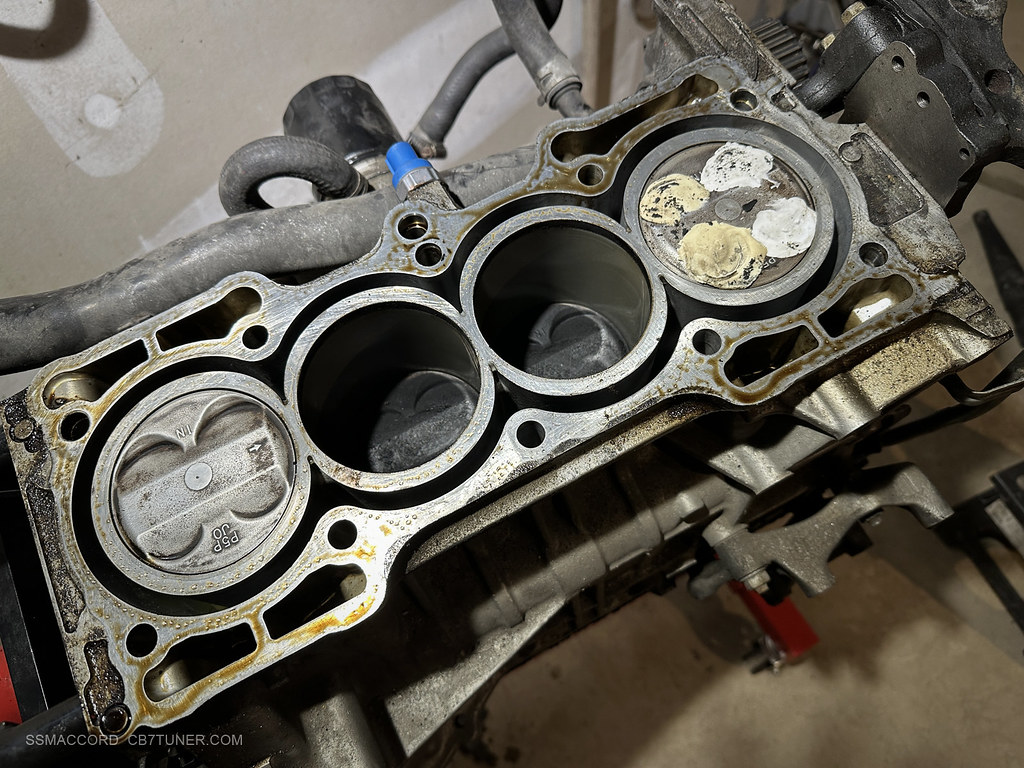
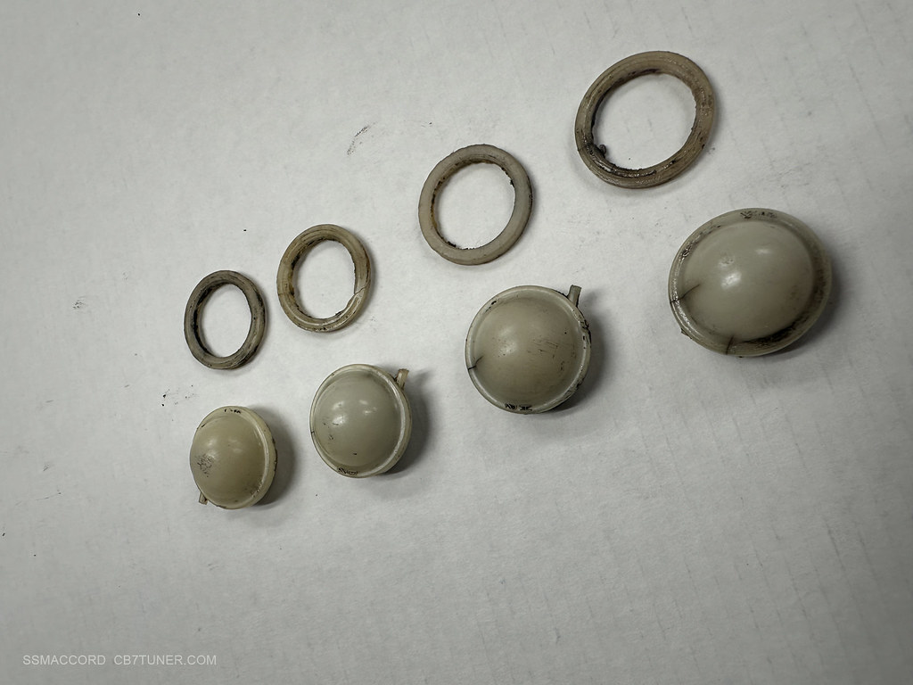
Upon trying to start the car the coolant got pumped into the engine and I hydro-locked it. It was a sad day, and a big lesson learned! I had to send the block off to a shop to have them fix my mess because I was young and had no clue what I was doing. I felt horrible as I killed the car. Now I label all hoses when removing the engine, unless it's obvious what goes where (like the alternator).

                              I always wanted the BB6 just because you can get the flywheel cover that bolts to the pan and also the transmission. But that pan has no oil baffles in it; so I told myself if I'm going to buy another oil pan I should get a racing one with proper baffles in it. So I'm jealous if you get this done as I always with I had a baffled BB6 pan with the flywheel protector plate. There's a shop that will weld these baffles into the pan for you?

                              Comment

                              Working...
                              X