Announcement

Collapse
No announcement yet.

Camber Adjustment Question

Collapse
X
 
  • Filter
  • Time
  • Show
Clear All
new posts

    #16
    Originally posted by sonikaccord View Post
    I'm not talking about a camber plate in the traditional sense. I mean taking johnl's suggestion, fabbing up a thick metal plate with the aforementioned slots so that you could move the pivot point of the UCA and keep some strength while allowing greater range of adjustment. It sounds like a great mod if done right.
    I'm not quite sure what you mean but note that 'slotting' the wishbone mounting holes won't result in "moving the pivot point", this can only be achieved by relocating the position of the chassis mounted pivot bushes (I believe there may be some aftermarket chassis mounts that have an adjustment that does this, i.e. move the centre of the bush in / out...?).

    Moving the whole wishbone in or out on slotted holes (but not changing the location of the centre of the pivoting bushes) will result in A) camber change, B) KPI change, and C) effective changing of the wishbone length. All of these things will have some differing dynamic affects, but B and C will IMO be of no great concern for a road car (something you live with or ignore for the sake of adjusting the static camber).

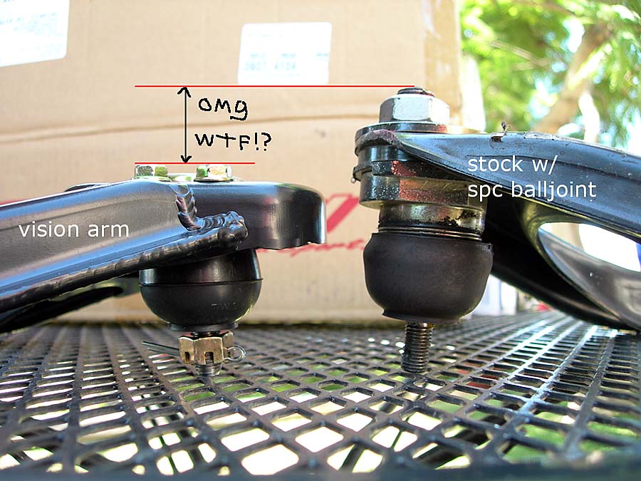
    If you mean making a wishbone where the ball joint itself is mounted in slots in the wishbone, then I think this would replicate at least one of the aftermarket adjustable wishbones, assuming what I've seen photos of is for a CB7 (and other models with more or less the same suspension), and not some other Honda.

    It would be possible to make custom tubular wishbones with slots at the chassis mount, but I'm not sure it would be any better than a modified (i.e. slotted) stock wishbone, the same limitations more or less would apply.

    There is no need to go overboard with fancy fabrication for the upper wishbones (e.g. tubular construction), they are subject to relatively low loadings so great strength / rigidity is not really needed. This low loading is a product of the distance from the contact patch to the lower ball joint relative to the distance of the upper ball joint to the lower ball joint, i.e. the 'load' is at the contact patch, the 'fulcrum' is at the lower ball joint, and the 'resistance' to the load is at the end of a long 'bar' that is the length of the distance from lower to upper ball joint (which is a lot longer than the distance from the contact patch to the lower ball joint). As such the leverage works for the upper wishbone not against it and loadings on it are relatively low.

    This is why upper ball joints typically last so long compared to lower ball joints despite the upper ball joints being quite small relative to the lower ball joints, (I need to replace an upper ball joint now, it's only died a few days ago and I'm fairly sure it's the original with 360,000km on it).
    Regards from Oz,
    John.

    Comment


      #17
      Originally posted by johnl View Post
      I'm not quite sure what you mean but note that 'slotting' the wishbone mounting holes won't result in "moving the pivot point", this can only be achieved by relocating the position of the chassis mounted pivot bushes (I believe there may be some aftermarket chassis mounts that have an adjustment that does this, i.e. move the centre of the bush in / out...?).
      Yes, I know that's the wrong nomenclature. My excuse was it was late and I had a few beers. :P I was thinking relative to the chassis you're moving the point.

      These are the closest thing I can think of to actually moving the "pivot point" but even then you are still moving the entire wishbone and not the actual fulcrum.

      Moving the whole wishbone in or out on slotted holes (but not changing the location of the centre of the pivoting bushes) will result in A) camber change, B) KPI change, and C) effective changing of the wishbone length. All of these things will have some differing dynamic affects, but B and C will IMO be of no great concern for a road car (something you live with or ignore for the sake of adjusting the static camber).
      We actually have dynamic suspension data on the accord. With some measurements it shouldn't be too hard to get that data.

      There is no need to go overboard with fancy fabrication for the upper wishbones (e.g. tubular construction), they are subject to relatively low loadings so great strength / rigidity is not really needed. This low loading is a product of the distance from the contact patch to the lower ball joint relative to the distance of the upper ball joint to the lower ball joint, i.e. the 'load' is at the contact patch, the 'fulcrum' is at the lower ball joint, and the 'resistance' to the load is at the end of a long 'bar' that is the length of the distance from lower to upper ball joint (which is a lot longer than the distance from the contact patch to the lower ball joint). As such the leverage works for the upper wishbone not against it and loadings on it are relatively low.
      This is interesting as I have never thought about it in a simple lever perspective. The fulcrum is closer the the load which gives the UCA a lot of "output" force relative to the "input". Is that right?

      Tubular wishbones should be reserved for show cars and full custom kit cars, imo. I have never seen an oem wishbone break from regular tracking. I was talking more along the lines of actually integrating the slots into the chassis to retain strength and rigidity in that area. That's where the plate comes into play. Just for reinforcement.

      Edit: This has kind of motivated to tear into my suspension theory book again.
      Last edited by sonikaccord; 07-23-2014, 09:04 PM.

      YouTube Clicky!!

      Comment


        #18
        While we're on this subject, my 3 year old TAS UBJs have gone bad, and in a horrible way. They are dry and rattling, worse yet the boots aren't torn either, just terrible POS's. So I need to get new UBJs. I currently have Ingalls anchor bolts. They squeak, I had to shave the UCAs, and they don't hold camber perfectly (they have slid on me a few times). And there's the built in problem of having an extra degree of freedom for doing alignments. Yes caster can be changed with the anchor bolt setup, but it makes everything else much more difficult. So while researching for SPC UBJs I cam across this image:


        Yes they are two different control arms, but the mounting location is still well shown. The SPC UBJ is much taller and inherently lowers the roll center of the car! Quite a bit. Lower roll center mean higher roll rate. What I don't know, but will soon find out, is if the Ingalls kit also affect the roll center.

        Summary: Do I stick with the Ingalls and deal with it (while getting new OE UPJs), or do I get the SPC kit and lower my roll center (making the car handle worse), or find another option?
        '93 H22A 5SPD SE - MRT - DIY-Turbo Sizing

        Comment


          #19
          It's something outrageous like a 20-30 mm difference between the OEM BJ and the SPC. I bought a new 3.0+ degree BJ kit and changed my mind after I received it. I now want the anchor bolt kit for the same reasons that you mentioned domesticated.

          But...you have a Charger now so you can hack up your CB to do damn near whatever. I say you do a diy on the johnl method of camber adjustment.


          Wait...I think I was picturing the wrong hole...(lol)

          Johnl was talking about the actual wishbone holes and I thought he was talking about the chassis holes.

          So what if you were to elongate the chassis holes and move the entire uca including the mounting points? The way I'm seeing it is you are still moving the BJ forward or backwards, keeping the same uca length. It will change the geometry, but any camber adjustment will do that...hmmm
          Last edited by sonikaccord; 07-23-2014, 09:20 PM.

          YouTube Clicky!!

          Comment


            #20
            Many people use Johnl's method. It's how you cheat in spec racing. We do it at work when trying to make small quick adjustments to mules. I think I'm going to try to collect some parts and model the kinematics of our car. There's a lot of good things about our suspension, but there are a lot of things I don't like.

            As far as tearing the car apart right now it will have to wait. I have some track days I need to attend to shake down the car before Gratton. It also has some new found issues I need to fix before I can even do the shakedown, such as UBJs.
            '93 H22A 5SPD SE - MRT - DIY-Turbo Sizing

            Comment


              #21
              Originally posted by sonikaccord View Post
              Yes, I know that's the wrong nomenclature. My excuse was it was late and I had a few beers. :P I was thinking relative to the chassis you're moving the point.

              These are the closest thing I can think of to actually moving the "pivot point" but even then you are still moving the entire wishbone and not the actual fulcrum.
              I'm still not sure what you mean...

              Originally posted by sonikaccord View Post
              We actually have dynamic suspension data on the accord. With some measurements it shouldn't be too hard to get that data.
              I've seen that page on this site, if it's the one you're referring to. I'm not sure how useful much of the information actually is, unless you were able to input it into a suspension simulation program such as 'Adams' (which I know little about).

              Scanning through it was interesting to see that the stock rear 'geometric roll centre' is lower than the front GRC, which is quite unusual (generally the rear GRC is nearly always higher than the front) but fits with my prior impression from simply looking at the linkage angles front vs rear suspension (i.e. my best guess without having actually plotted the GRC locations has been that the rear GRC looked likely to be lower than the front).

              If there were a reasonably easy way to raise the rear GRC (not too much, overly high GRCs can cause big problems) then it's something I'd be interested in doing as it's likely to improve steering response among other things. I don't think there would be an easy way though, other than raising the rear end of the chassis relative to the front.

              Originally posted by sonikaccord View Post
              This is interesting as I have never thought about it in a simple lever perspective. The fulcrum is closer the the load which gives the UCA a lot of "output" force relative to the "input". Is that right?
              I think we're on the same page. Forces at the upper wishbone are particularly low on the CB7 (et al) due to the upper wishbone being mounted so high in the chassis with a tall suspension 'upright', other designs with a shorter 'upright' mounted lower in the chassis will have greater forces at the upper wishbone. Note that the greatest forces acting (laterally) on the suspension are compressive forces seen in the LCA while the greatest lateral force the upper wishbone sees are tensile forces (compressive force X requires a much stiffer member to resist than tensile force X).

              Originally posted by sonikaccord View Post
              Tubular wishbones should be reserved for show cars and full custom kit cars, imo. I have never seen an oem wishbone break from regular tracking. I was talking more along the lines of actually integrating the slots into the chassis to retain strength and rigidity in that area. That's where the plate comes into play. Just for reinforcement.
              There's nothing wrong with using a stronger wishbone, just that it's a lot of trouble for something that isn't really needed.

              Slotting the two bush mount post holes in the chassis itself would be very difficult to do. Have a good look and you'll see why.
              Regards from Oz,
              John.

              Comment


                #22
                Originally posted by domesticated View Post
                Yes caster can be changed with the anchor bolt setup, but it makes everything else much more difficult.
                By "anchor bolt setup" I assume you mean chassis mounts with a slotted adjustment in the mounts themselves? If so then yes, adjusting them both to the same degree would result in camber change, adjusting them individually (i.e. one in / out, or one in and one out etc.) would result in caster change as well as camber change (or no camber change, depending on exactly how the adjustment is made).

                Note that eccentrically adjustable ball joints also change both camber and caster, I've written something on this here:
                http://www.cb7tuner.com/vbb/showthre...t=48011&page=3


                Originally posted by domesticated View Post
                Yes they are two different control arms, but the mounting location is still well shown. The SPC UBJ is much taller and inherently lowers the roll center of the car! Quite a bit. Lower roll center mean higher roll rate. What I don't know, but will soon find out, is if the Ingalls kit also affect the roll center.
                If the centres of the 'balls' in the two joints are at the same height relative to top of the suspension 'upright' then the geometry will be unchanged, regardless of whether the apparent angle of the wishbone arm itself is no longer at the same angle (the geometry is determined by the axis of the chassis pivot and the centre of the ball joint ball, not the apparent angle of the wishbone arm).

                From what I see in the photo it looks likely that the balls in the respective joints are probably at a similar height, the difference in apparent length of the two joints being accounted for by the eccentric adjusting mechanism. However I don't have the joints in my hands so can't tell for certain.

                Originally posted by domesticated View Post
                Summary: Do I stick with the Ingalls and deal with it (while getting new OE UPJs), or do I get the SPC kit and lower my roll center (making the car handle worse), or find another option?
                If the adjustment you already have has a tendency to move, then it's not a good thing and I'd be looking for something different.

                If we were to assume (for the sake of argument) that the centre of the upper wishbone ball were to be raised, then this would make the effective angle of the upper wishbone steeper (angling more downward toward the chassis mounts). This will shorten the length of the 'effective swing arm' (a geometric construction based on the relative angles of the upper and lower wishbones, and the point at which the axes of the extrapolated wishbone 'lines' converge). This will raise the front geometric roll centre, not lower it.

                As discussed briefly above, the CB7 front roll centre already appears to be rather high relative to the rear GRC, so it might not be changing things in the right direction...

                If you do a search for 'effective swing arm' and 'geometric roll centre' then you'll probably find some good diagrams of this fairly easily. Be aware though that this is entering a complex and widely poorly understood area of chassis dynamics that affects weight transfer and the speed with which weight transfers (i.e. geometric roll stiffness vs elastic roll stiffness etc. etc.) , it's not nearly as simple as presented in many popular books...
                Last edited by johnl; 07-23-2014, 11:12 PM.
                Regards from Oz,
                John.

                Comment


                  #23
                  I got my alignment done, I have a little bit of a negative camber. I've decided I'm going to get some SPCs in the front, and a kit Megan has for the back upper and lower controls arms. It's on ebay some where. It will be a minute now before I get these arms. I've found out I have more issues than I wanted to know with a fairly new part failing motor side.
                  For Sale Thread CLICK HERE!

                  1991 CB9 EX Wagon

                  1990 CB7 EX Sedan

                  1997 RA1 LX Wagon

                  CB7Tuner Discord CLICK ME! -- http://www.cb7tuner.com/vbb/showthre...02#post3285402

                  Comment


                    #24
                    Originally posted by johnl View Post
                    By "anchor bolt setup" I assume you mean chassis mounts with a slotted adjustment in the mounts themselves? If so then yes, adjusting them both to the same degree would result in camber change, adjusting them individually (i.e. one in / out, or one in and one out etc.) would result in caster change as well as camber change (or no camber change, depending on exactly how the adjustment is made).

                    Note that eccentrically adjustable ball joints also change both camber and caster, I've written something on this here:
                    http://www.cb7tuner.com/vbb/showthre...t=48011&page=3


                    If the centres of the 'balls' in the two joints are at the same height relative to top of the suspension 'upright' then the geometry will be unchanged, regardless of whether the apparent angle of the wishbone arm itself is no longer at the same angle (the geometry is determined by the axis of the chassis pivot and the centre of the ball joint ball, not the apparent angle of the wishbone arm).

                    From what I see in the photo it looks likely that the balls in the respective joints are probably at a similar height, the difference in apparent length of the two joints being accounted for by the eccentric adjusting mechanism. However I don't have the joints in my hands so can't tell for certain.


                    If the adjustment you already have has a tendency to move, then it's not a good thing and I'd be looking for something different.

                    If we were to assume (for the sake of argument) that the centre of the upper wishbone ball were to be raised, then this would make the effective angle of the upper wishbone steeper (angling more downward toward the chassis mounts). This will shorten the length of the 'effective swing arm' (a geometric construction based on the relative angles of the upper and lower wishbones, and the point at which the axes of the extrapolated wishbone 'lines' converge). This will raise the front geometric roll centre, not lower it.

                    As discussed briefly above, the CB7 front roll centre already appears to be rather high relative to the rear GRC, so it might not be changing things in the right direction...

                    If you do a search for 'effective swing arm' and 'geometric roll centre' then you'll probably find some good diagrams of this fairly easily. Be aware though that this is entering a complex and widely poorly understood area of chassis dynamics that affects weight transfer and the speed with which weight transfers (i.e. geometric roll stiffness vs elastic roll stiffness etc. etc.) , it's not nearly as simple as presented in many popular books...
                    That's a good point on the SPC UBJ. I glossed over that when looking around last night. Depending on the angle at which you install the UBJ the effect on caster and camber is a resultant relationship. I was just stating the anchor bolts are a PITA to tune because of the extra degree of freedom.

                    As far as the roll center you're right about that I drew a picture, I can't upload now because I'm at work, but reducing the swing arm length forces the rotational center inward, which stepped the path from the tire patch to the roll center, in turn moving the roll center slightly upward. It's been a while since I to design suspension kinematics and mostly what I do now I low level changes like bushing, shock, spring, and stabar changes.

                    I'm going to go home and measure the length of the kingpin axes. 1 degree/cm is a pretty close guess for adjusting caster camber.
                    '93 H22A 5SPD SE - MRT - DIY-Turbo Sizing

                    Comment


                      #25
                      Here it is.
                      '93 H22A 5SPD SE - MRT - DIY-Turbo Sizing

                      Comment


                        #26
                        Nice triangle work there.

                        I'm out of my specialty here, so does that minor increase in roll center height have a large effect on the overall system?

                        YouTube Clicky!!

                        Comment


                          #27
                          Originally posted by sonikaccord View Post
                          Nice triangle work there.

                          I'm out of my specialty here, so does that minor increase in roll center height have a large effect on the overall system?
                          Maybe. It's also a maybe as to weather or not the the effect is good or bad as JohnL mentioned earlier. I don't know enough about the kinematics of the car to make that judgement and I haven't look at the SPMM charts in a while. So I'm going to do more digging. In the mean time I'm going to order the SPC ball joint I think. I need to replace my upper ball joint anyway and all I can find is OE uppers for 180, but I don't need the control arm or the anchor bolts and bushings, just the ball joint.
                          '93 H22A 5SPD SE - MRT - DIY-Turbo Sizing

                          Comment


                            #28
                            I have a pair of BJs I'm about to throw in the classifieds in a minute. I offered them to one member here, but their priorities may be changed to something else. Once he gives me an update, I'll post them.

                            Also, when I installed them at max adjustment, they hit the inner lip of the fender. I just kind of sat them in there and moved the control arm up, but it looks like clearance is tight if they are maxed out. Then I said screw it, I'm going for performance not "stance."
                            Last edited by sonikaccord; 07-24-2014, 09:17 PM.

                            YouTube Clicky!!

                            Comment


                              #29
                              Originally posted by domesticated View Post
                              That's a good point on the SPC UBJ.
                              Increasing caster is generally a 'Good Thing', so if I were using such ball joints I would orient the joint in such a manner that the 'upright' is angled more rearward (at the desired camber angle) rather than in such a manner that the 'upright' is more vertical.

                              The only other easily practicable means to increase caster angle is to modify the radius rod (i.e. the suspension member attached to the front of the subframe and the LCA) by shortening it's effective length. This involves modifying the forward end of the radius rod so that it can pass further forward through the bush in the subframe.

                              If a large caster angle is achieved this way then the wheelbase will be measurably lengthened (wheel forward relative to chassis), which could be a good or bad thing (or even both a good and bad thing in different ways), but probably not a big thing either way (no apparent issues with my car). This does misalign the LCA chassis mount bush relative to the chassis bolt, but these 'Silentbloc' style bushes can cope with significant misalignment quite well. Having said that, poly bushes don't cope nearly as well as rubber bushes...

                              Note that large changes in caster also cause the height of the tie-rod end to rise or lower (when increasing caster, to lower), and this can introduce significant bump and roll steer. Nearly all production cars have some degree of 'roll understeer' designed into the steering geometry so that as the suspension goes into 'bump' (or 'jounce' or whatever we call it - the wheel moving upward relative to the chassis) the wheel will toe-out, and when the suspension goes into 'droop' ('rebound' etc.) the wheel will gain toe-in. This means that as the outside suspension goes into 'bump' the wheel toes-out and as the inside wheel 'droops'' the wheel toes-in, causing an understeering effect as the body rolls during cornering.

                              Lowering the tie-rod end moves this effect toward the opposite affect, i.e. the wheel can gain toe-in when the suspension goes into bump and toe-out when the suspension goes into rebound. This can cause a roll-oversteer affect because as the chassis rolls the front wheels 'steer' more than the driver intended. This might sound as if it could be 'good', but from personal experience it isn't, it's disconcertingly 'non-linear'. To correct this problem with my car (now approximately 6° of caster rather than about the stock 2°, or so) I had to lower the steering rack to account for the lowering of the tie-rod ends.

                              Originally posted by domesticated View Post
                              As far as the roll center you're right about that I drew a picture, I can't upload now because I'm at work, but reducing the swing arm length forces the rotational center inward, which stepped the path from the tire patch to the roll center, in turn moving the roll center slightly upward.
                              The more observant might have noticed that I said "effective swing arm", when the more accepted term is 'virtual swing arm'.

                              While I'm cleaning my house, I also said that; "This is why upper ball joints typically last so long compared to lower ball joints despite the upper ball joints being quite small relative to the lower ball joints". I should have said; "This is at least one of the reasons why...". The lower ball joints also carry the chassis load, which contributes to earlier wear.

                              Originally posted by domesticated View Post
                              I'm going to go home and measure the length of the kingpin axes. 1 degree/cm is a pretty close guess for adjusting caster camber.
                              It's not a guess, it's a measurement based on the distance between the centres of the upper and lower joint 'balls'. The only 'guess' is that I had to estimate the location of the centre of the balls (hidden within the joint) since I wasn't about to cut them open to make a more precise measurement. I'm sure the 1cm = 1° is quite accurate enough for all practical purposes.
                              Last edited by johnl; 07-24-2014, 11:59 PM.
                              Regards from Oz,
                              John.

                              Comment


                                #30
                                Originally posted by domesticated View Post
                                Here it is.
                                Note that (as you're probably aware) the effect is similar whether the outer end of the wishbone is raised or the inner end is lowered (anything that increases the downward rake toward the chassis). So, it's also an issue when the ride height is reduced.

                                Countering this, the effect is the opposite at the lower 'wishbone', i.e. raising the ball joint (if this were possible) or lowering the chassis pivot (anything that that increases the downward rake toward the chassis) causes the 'virtual swing arm to lengthen and thus the GRC to lower. If you really need to know what happens to the GRC when lowering the chassis then a reasonably accurately dimensioned detailed suspension schematic is needed.
                                Regards from Oz,
                                John.

                                Comment

                                Working...
                                X