This is a highly recommended upgrade to any CB7 suspension. It is affordable (about $150), fairly easy to install, well made, and most importantly adds a whole new dimension of balance to the way the car handles.
The downsides are:
1) It is significantly heavier than the stock bar. Given the plusses, this isn't a huge deal, but it is there.
2) The installation instructions provided could be clearer. I can see it being a daunting task for someone relatively new to modifying cars.
3) It DOES NOT bolt up to the stock locations, so some modification of the rear subframe will be required.
4) It is quite a bit larger than the stock bar 14mm vs 22mm or roughly 60% larger, so it may not clear all setups. Fitment is on an individual basis. Having said that, it DOES provide more exhaust clearance than the stock bar.
The comparison:
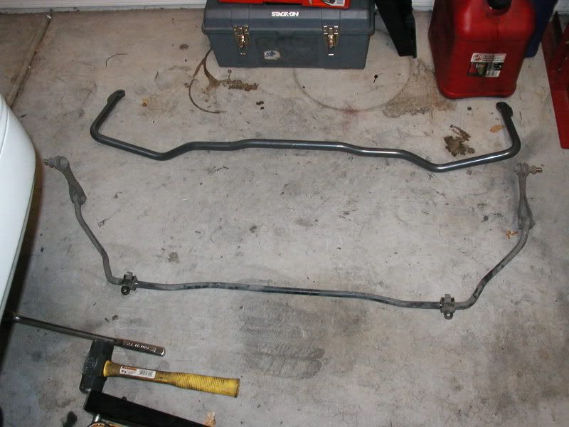
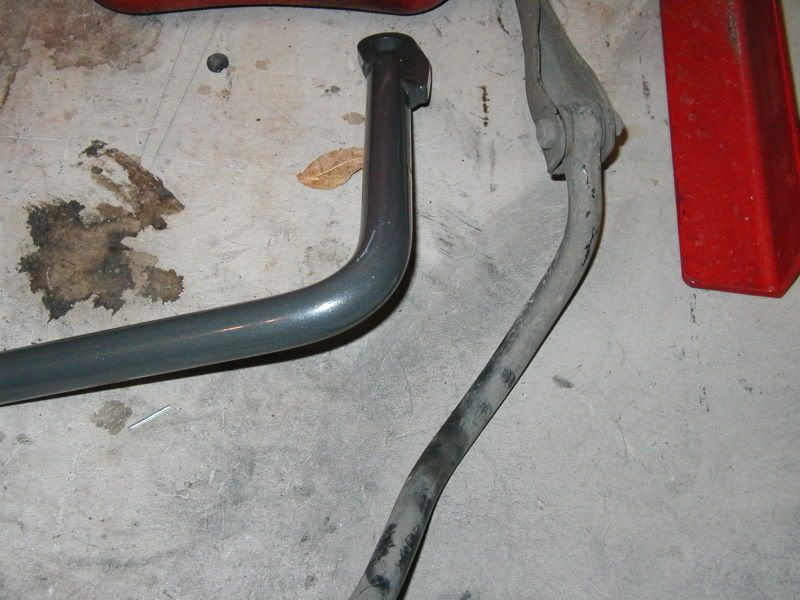
You can clearly see the larger size of the new bar.
Included with bar:
Instruction sheet - 1
Anti-roll Bar - 1
U bracket - 2
Angle bracket - 2
1/4 spacer - 4
Backing plate - 2
Pivot bushing (for the end links) - 2
Grommet (for the end links)- 8
Cup Washer (for the end links) - 8
3/8 ID sleeve (for the end links) - 2
3/8-16 x 6.00 Hex bolt (for the end links) - 2
3/8-16 x 1 Hex bolt - 2
3/8-16 nylon luck nut - 4
3/8 flat washer - 4
5/16-18 x 1.00 hex bolt - 4
5/16-18 x 1.50 hex bolt - 2
5/16-18 nylon lock nut - 4
5/16 flat washer - 8
Polyurethane grease tube - 1
You will need the following tools:
1/2" socket
1/2" open end wrench
9/16" socket
9/16" open end wrench
12MM socket
14MM socket
19MM socket
Drill
5/16" drill bit
Marker/paint/chalk
To begin:
1) Park the vehicle on a smooth level surface, block the front wheels and raise the rear of the vehicle. Remove the rear wheels.
2) Remove the bolts that hold the stock sway bar to the rear subframe.
3) Lower the suspension down onto jackstands, so that the weight of the vehicle is being supported by the suspension and NOT the frame of the car. This will allow you to work with the car at ride height which unloads the sway bar.
4) Remove the two bolts that secure the stock way bar to the trailing arms and remove the stock sway bar. Remove the 2 subframe brackets that held the "D" shaped pivot bushing for the stock bar. There are 3 14mm bolts holding each one on. This will keep them from interfering with the new bar, and they are no longer needed.
Here is what it looks like with the Progress bar and the bracket in place. Notice that the bar is touching this bracket:
The interference is marked in yellow, while the bracket bolts are marked in red:
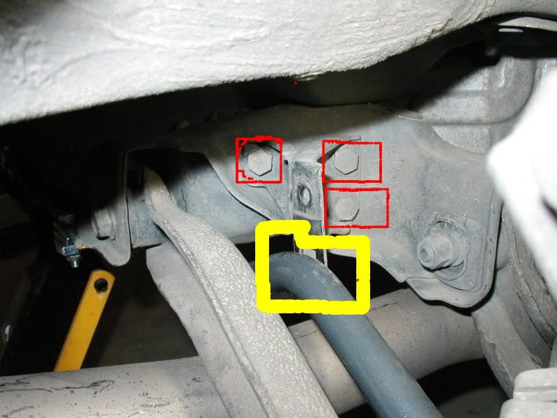
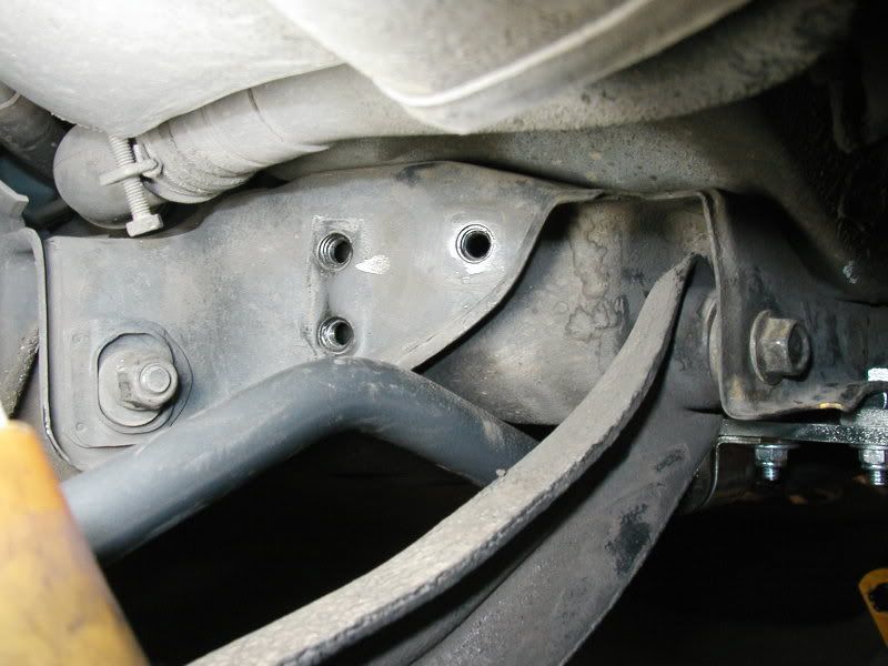
This is what it looks like with the bracket gone:
5) Secure the angle brackets to the trailing arms, using the 3/8-16 x 1.00 hex bolts, 2 3/8 flat washers per side and 2 3/8 nylon locking nuts. You will need a washer on each side as illustrated below:
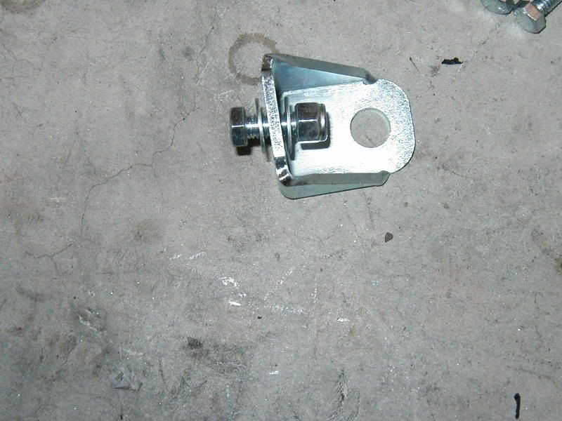
DO NOT TIGHTEN THESE FULLY AT THIS POINT. Some modification of the brake line mounting tab may be required (mine did not, so it may be a rear drum thing).
6) Assemble the end links for each side as shown and secure them to the angle brackets you just installed.
You will need the following for EACH end link:
3/8-16 x 6.00 bolt
4 polyurethane grommets (make sure the ridges on the poly face each other)
3/8" I.D. sleeve
4 cup washers (make sure the "cup" of the washer is on the bushing)
3/8-16 nylon lock nut
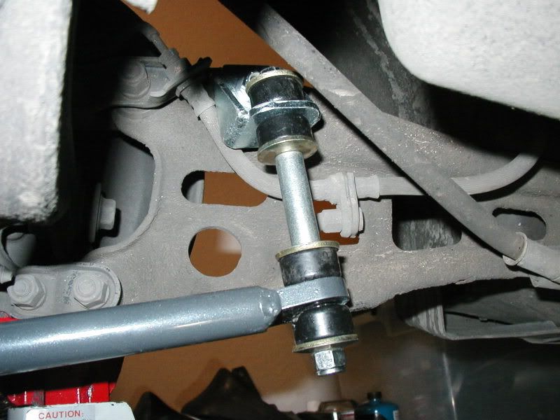
Lift the ends of the swaybar into position and place a 3/8-16 nylon lock nut on the end of each end link. DO NOT TIGHTEN THEM AT THIS POINT.
7) Lubricate the "D" shaped pivot bushings using the supplied grease tube and snap them over the bar. They should locate just outside the bend in the middle of the bar.
8) Assemble the backing plate and 1/4" spacers together, place the assembly on top of the "D" shaped pivot bushing and put the pivot bushing bracket over the poly bushing.
You will need to lift the bar up to the rear subframe at this point, and make sure it is sitting where it is going to be mounted. I highly recommend using a jackstand to support the bar as close to the mounting position as possible, as it will make the next step much easier.
9) With the bar up to the subframe and the backing plate, spacers and bushing bracket assembled around it, mark off the 4 holes that will need to be drilled in the subframe. You can feel the large lip you will be drilling through if you put your finger on the top side of the subframe. You want to make sure that the holes you drill are located on this lip. The backing plate should make it pretty obvious about where you need to drill. Mark the holes with a marker, chalk, paint etc. Repeat for the other side.
Here is an assembled approximation of what you will be doing:
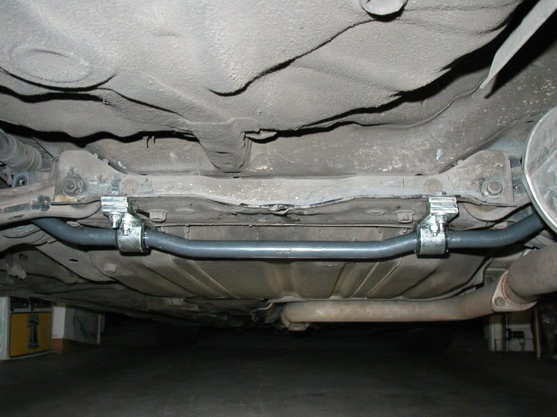
10) Lower the bar out of the way. Using a 5/16" drill bit, drill out the 4 holes you just marked.
It should look roughly like this:
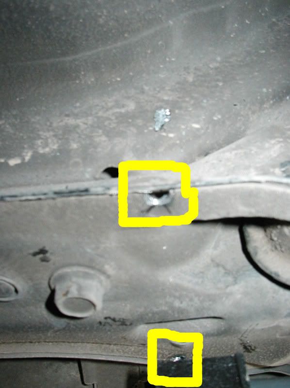
Here is a clearer image of the front hole (by the gas tank):
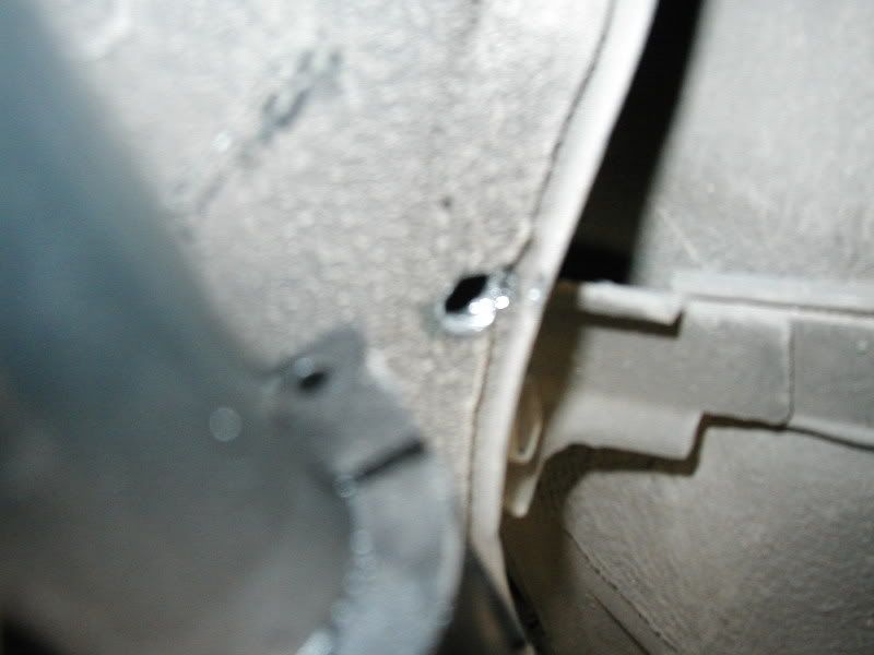
11) Once the holes are drilled, you can lift everything back into place and reassemble, making sure that there are 2 1/4" spacers at each rear hole on the subframe, and ZERO on the front hole.
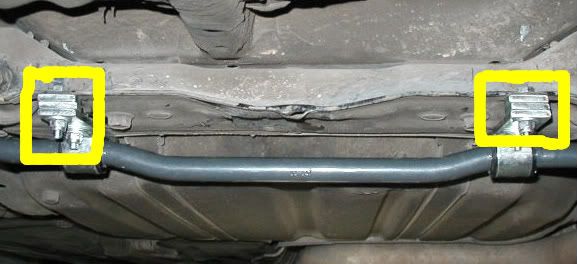
* Remember, the REAR hole identifies the one closest to the rear of the car.
12) To assemble and secure each bar bracket assmebly:
A) Place 1 5/16-18 x 1.00 hex bolt through each front subframe hole.
B) Place 1 5/16-18 x 1.00 and 1 5/16 flat washer in the middle hole on the bracket with the threads facing the ground.
C) Place 1 5/16-18 x 1.50 hex bolt through the rear subframe hole.
D) lift the backing plate into place, with the spacers for the rear hole. Place the pivot bushing bracket over the front and middle hole in the backing plate, place 1 5/16" flat washer on all three bolts. Place 1 5/16 nylon locking nut on each bolt, and then tighten.
13) Once everything is bolted up, you can go around and tighten all of the bolts. Start with the backing plates, then the front bushing pivot bracket bolts, the angle brackets mounted to the trailing arms, and finally, the end links.
*The proper way to tighten the end links is to tighten just until you can no longer rotate the cup washers by hand, and then 1 more complete turn. Do not overtorque as this will lead to shortened bushing life.
14) Jack the car up to release the rear suspension, reinstall rear tires, and torque lug nuts to spec. Lower the car.
15) Push or drive the car around to settle the suspension, and then double check tightness. Tightness should also be checked periodically to ensure safety.
The finished product:

Enjoy. It is well worth the money and effort.
The downsides are:
1) It is significantly heavier than the stock bar. Given the plusses, this isn't a huge deal, but it is there.
2) The installation instructions provided could be clearer. I can see it being a daunting task for someone relatively new to modifying cars.
3) It DOES NOT bolt up to the stock locations, so some modification of the rear subframe will be required.
4) It is quite a bit larger than the stock bar 14mm vs 22mm or roughly 60% larger, so it may not clear all setups. Fitment is on an individual basis. Having said that, it DOES provide more exhaust clearance than the stock bar.
The comparison:


You can clearly see the larger size of the new bar.
Included with bar:
Instruction sheet - 1
Anti-roll Bar - 1
U bracket - 2
Angle bracket - 2
1/4 spacer - 4
Backing plate - 2
Pivot bushing (for the end links) - 2
Grommet (for the end links)- 8
Cup Washer (for the end links) - 8
3/8 ID sleeve (for the end links) - 2
3/8-16 x 6.00 Hex bolt (for the end links) - 2
3/8-16 x 1 Hex bolt - 2
3/8-16 nylon luck nut - 4
3/8 flat washer - 4
5/16-18 x 1.00 hex bolt - 4
5/16-18 x 1.50 hex bolt - 2
5/16-18 nylon lock nut - 4
5/16 flat washer - 8
Polyurethane grease tube - 1
You will need the following tools:
1/2" socket
1/2" open end wrench
9/16" socket
9/16" open end wrench
12MM socket
14MM socket
19MM socket
Drill
5/16" drill bit
Marker/paint/chalk
To begin:
1) Park the vehicle on a smooth level surface, block the front wheels and raise the rear of the vehicle. Remove the rear wheels.
2) Remove the bolts that hold the stock sway bar to the rear subframe.
3) Lower the suspension down onto jackstands, so that the weight of the vehicle is being supported by the suspension and NOT the frame of the car. This will allow you to work with the car at ride height which unloads the sway bar.
4) Remove the two bolts that secure the stock way bar to the trailing arms and remove the stock sway bar. Remove the 2 subframe brackets that held the "D" shaped pivot bushing for the stock bar. There are 3 14mm bolts holding each one on. This will keep them from interfering with the new bar, and they are no longer needed.
Here is what it looks like with the Progress bar and the bracket in place. Notice that the bar is touching this bracket:
The interference is marked in yellow, while the bracket bolts are marked in red:

This is what it looks like with the bracket gone:

5) Secure the angle brackets to the trailing arms, using the 3/8-16 x 1.00 hex bolts, 2 3/8 flat washers per side and 2 3/8 nylon locking nuts. You will need a washer on each side as illustrated below:

DO NOT TIGHTEN THESE FULLY AT THIS POINT. Some modification of the brake line mounting tab may be required (mine did not, so it may be a rear drum thing).
6) Assemble the end links for each side as shown and secure them to the angle brackets you just installed.
You will need the following for EACH end link:
3/8-16 x 6.00 bolt
4 polyurethane grommets (make sure the ridges on the poly face each other)
3/8" I.D. sleeve
4 cup washers (make sure the "cup" of the washer is on the bushing)
3/8-16 nylon lock nut

Lift the ends of the swaybar into position and place a 3/8-16 nylon lock nut on the end of each end link. DO NOT TIGHTEN THEM AT THIS POINT.
7) Lubricate the "D" shaped pivot bushings using the supplied grease tube and snap them over the bar. They should locate just outside the bend in the middle of the bar.
8) Assemble the backing plate and 1/4" spacers together, place the assembly on top of the "D" shaped pivot bushing and put the pivot bushing bracket over the poly bushing.
You will need to lift the bar up to the rear subframe at this point, and make sure it is sitting where it is going to be mounted. I highly recommend using a jackstand to support the bar as close to the mounting position as possible, as it will make the next step much easier.
9) With the bar up to the subframe and the backing plate, spacers and bushing bracket assembled around it, mark off the 4 holes that will need to be drilled in the subframe. You can feel the large lip you will be drilling through if you put your finger on the top side of the subframe. You want to make sure that the holes you drill are located on this lip. The backing plate should make it pretty obvious about where you need to drill. Mark the holes with a marker, chalk, paint etc. Repeat for the other side.
Here is an assembled approximation of what you will be doing:

10) Lower the bar out of the way. Using a 5/16" drill bit, drill out the 4 holes you just marked.
It should look roughly like this:

Here is a clearer image of the front hole (by the gas tank):

11) Once the holes are drilled, you can lift everything back into place and reassemble, making sure that there are 2 1/4" spacers at each rear hole on the subframe, and ZERO on the front hole.

* Remember, the REAR hole identifies the one closest to the rear of the car.
12) To assemble and secure each bar bracket assmebly:
A) Place 1 5/16-18 x 1.00 hex bolt through each front subframe hole.
B) Place 1 5/16-18 x 1.00 and 1 5/16 flat washer in the middle hole on the bracket with the threads facing the ground.
C) Place 1 5/16-18 x 1.50 hex bolt through the rear subframe hole.
D) lift the backing plate into place, with the spacers for the rear hole. Place the pivot bushing bracket over the front and middle hole in the backing plate, place 1 5/16" flat washer on all three bolts. Place 1 5/16 nylon locking nut on each bolt, and then tighten.
13) Once everything is bolted up, you can go around and tighten all of the bolts. Start with the backing plates, then the front bushing pivot bracket bolts, the angle brackets mounted to the trailing arms, and finally, the end links.
*The proper way to tighten the end links is to tighten just until you can no longer rotate the cup washers by hand, and then 1 more complete turn. Do not overtorque as this will lead to shortened bushing life.
14) Jack the car up to release the rear suspension, reinstall rear tires, and torque lug nuts to spec. Lower the car.
15) Push or drive the car around to settle the suspension, and then double check tightness. Tightness should also be checked periodically to ensure safety.
The finished product:

Enjoy. It is well worth the money and effort.






Comment