
SUSP: Rebuild Steering Gear (Rack and Pinion) Assembly
This procedure is to rebuild your power steering rack. This one was still working properly, but the boots were completely split open and the rack was leaking. I suppose it is easier (and maybe more cost effective) to purchase a rebuilt one; I had heard some horror stories about aftermarket racks, so I decided to rebuild mine with OEM parts. This procedure assumes that the power steering rack has already been removed from the car: http://www.cb7tuner.com/vbb/showthread.php?t=30228 I screwed up and forgot to take a few pictures along the way. It is highly recommended that you have the appropriate pages of the factory service manual available when doing this.
Tools needed:
10 mm socket
12 mm socket
14 mm socket
17 mm open end wrench
Crescent wrench
Snap ring pliers
Small chisel or punch
Flat bladed screwdriver
Large channel locks
Hammer
Supplies:
065A3-SM4-435 steering gearbox seal kit (6/21/2017: these kits may no longer be available from HONDA)
065B3-SM4-405 steering valve body seal kit
Inner tie rod ends (2)
Tie rod boots (2)
Tie rod boot bands (2)
Honda Power Steering grease 08733-B070E
Brake cleaner
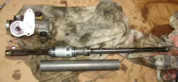
 DSC01388 by Paul Kemme, on Flickr
Reference figures from Majestic; I noticed that it doesn't show the pinion retainer:


Clean the outside of the unit prior to starting disassembly; if necessary use a tooth brush with brake cleaner or even a wire brush to remove caked on dirt.
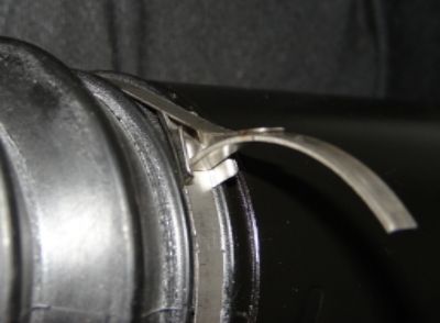
Remove the nut from the inner tie rod. Undo the bent over tabs on the tie rod boot straps, remove the straps. Remove the spring clamp where the boot attaches to the inner tie rod end, then remove the boots.
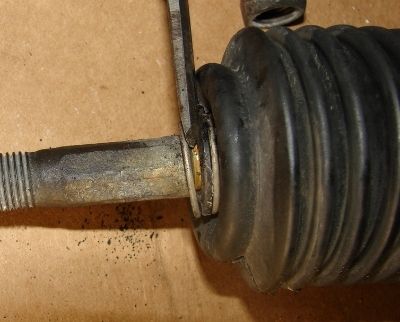
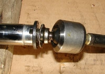
The inner tie rods are secured with a bent washer, use a screwdriver or small chisel to flatten the bent portion of these washers.
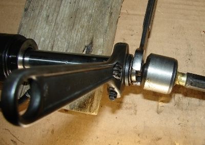
Using a crescent wrench on the flats on the end of the rack and a 17 mm wrench on the tie rod base, remove the inner tie rods from the rack. If the outer end of the tie rod does not sag when holding the inner end horizontal, then it is probably still good. If you’re going to this extent, it is a good idea to go ahead and install new inner tie rods.
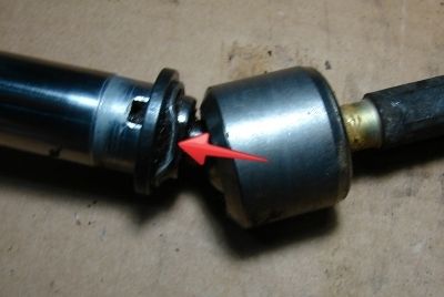
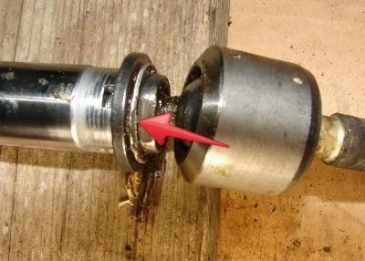
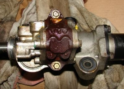
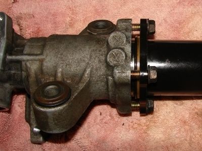
Remove the two bolts mounting the valve body to the gear box. There are two orifices in ports on the valve body that are not secured, remove them and put them where you won’t lose them. I like to use shallow cardboard boxes as project boxes to hold parts.
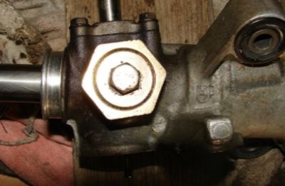
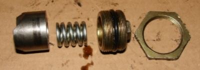
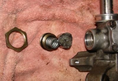
Use channel locks (or a large crescent wrench) to loosen the locknut on the rack guide screw; then a 14 mm socket to remove the rack guide screw, then remove the spring and rack guide.
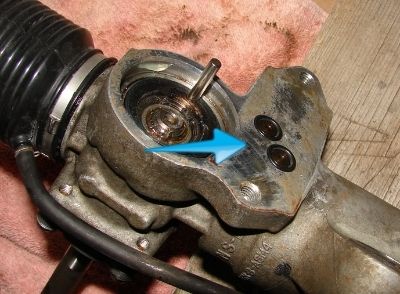
Use the snap ring pliers to remove the small snap ring on the exposed end of the pinion shaft.
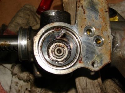
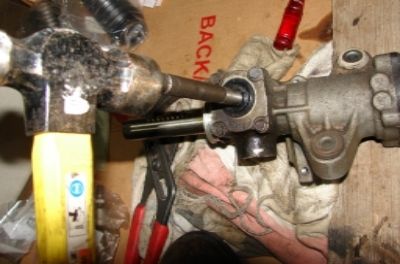
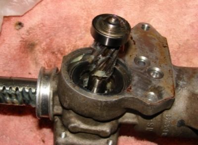
Turn the unit over and tap lightly on the end of the pinion shaft to drive the pinion shaft and bearing assembly out of the gear housing.
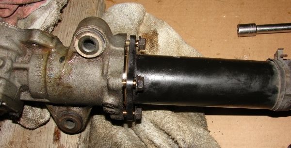
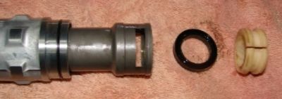
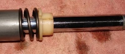
Using a 12 mm socket, remove the four bolts attaching the cylinder housing to the gear housing. This is spring loaded, so remove them evenly a little at a time. Separate the cylinder housing from the gear housing. There is a spring and Teflon bushing inside the end of the cylinder housing, these should pretty much fall out, but they may remain on the rack - remove them. From the right end of the outer cylinder, push the shaft seal toward the inside to remove it.
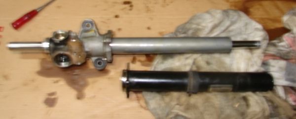
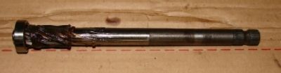
Slide the inner cylinder off the rack; then remove the rack assembly from the housing.
Remover the seal retainer and cylinder cap assembly from the rack. There is a snap ring on the seal retainer that keeps it from coming out of the cylinder cap; I didn’t see a reason to separate them – I could access the o-rings on both parts, so I did not remove the ring and separate these two parts.
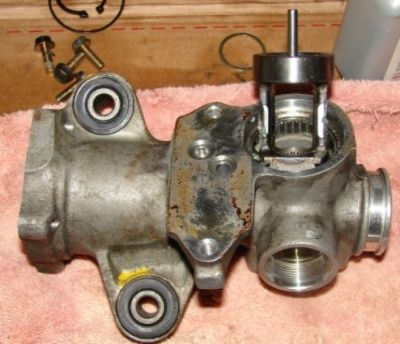
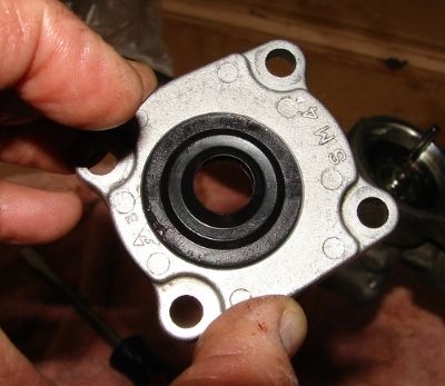
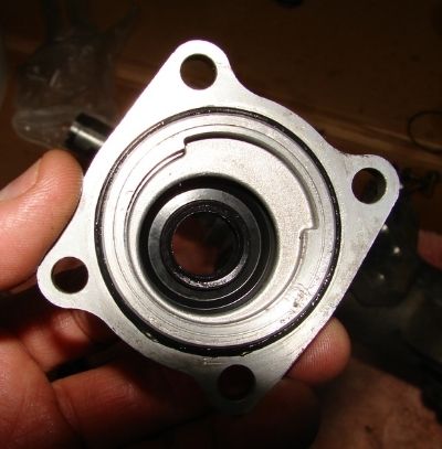
Remove the four bolts holding the gear housing cap; remove the cap. (Note: this picture was taken during assembly; the pinion shaft is not there at this point of disassembly.)

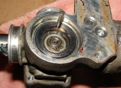
Remove the snap ring on the pinion holder, then remove the pinion holder from the gear housing.
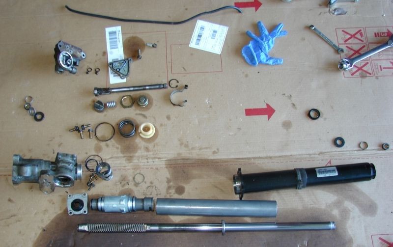
Everything disassembled:
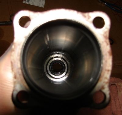
Clean the old grease from the pinion upper bearing. Pack the bearing as best you can with new grease. Install the pinion holder. Install the snap ring on the end of the pinion holder.
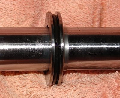
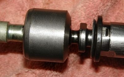
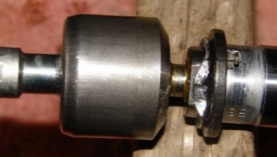
On the rack, install a new piston seal. This seal has a triangular cross section, the tip should be pointed up. Install a new piston ring over this seal. There are Honda tools to stretch the ring over the piston, then to resize it. I warmed it with a hair dryer and was able to gently stretch it over the piston, then compress and straighten it with my fingers.

Remove the large clip from the seal retainer; remove rack bushing B and the cylinder end seal.
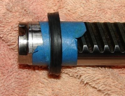
After greasing the rack surface, install bushing B on the toothed end of the rack against the piston. Honda has a tool to install the new end seal over the toothed section of the rack; I simply wrapped the end of the rack with masking tape, sticky side out, then slipped the seal over that. Slide the seal and tape over the rod over to the bushing. The open face of the seal should face the bushing.
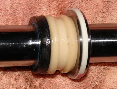
Install new o-rings on the seal retainer and cylinder cap. Install the seal retainer over the seal and bushing on the rack. Install the retainer clip.
Install the retaining washer in the gear housing.
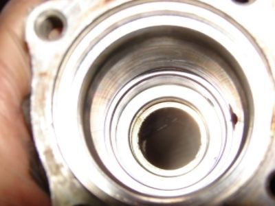
Generously grease the toothed end of the rack, lubricate the o-rings with power steering fluid (or PS grease) then install the rack with seal retainer and cylinder cap into the gear housing.
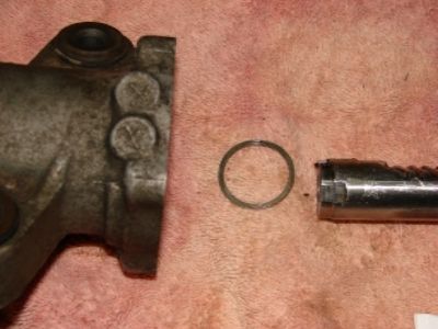
Generously lubricate the inside diameter of the cylinder with power steering fluid, carefully install it past the piston seal, then onto the end of the cylinder cap.
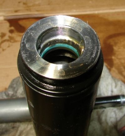
Lightly grease the non-toothed end of the rack. Install the spring and bushing A. Install the cylinder end seal in the end of the cylinder housing from the inside. I dropped it in, then used my finger from the outside end to position the seal. The open face of the seal should face inside.
Install the backup ring (you can reuse this part) and a new o-ring on the cylinder housing. Wrap the end of the rack in masking tape and lubricate the tape with grease. Install the cylinder housing over the rack and carefully guide the end of the rack through the seal. Push the cylinder housing into the gear housing and install the four bolts. Torque the bolts evenly to 16 ft-lb.
Generously lubricate the pinion gear and bearing with PS grease and install in the pinion holder. Install the snap ring to retain it.
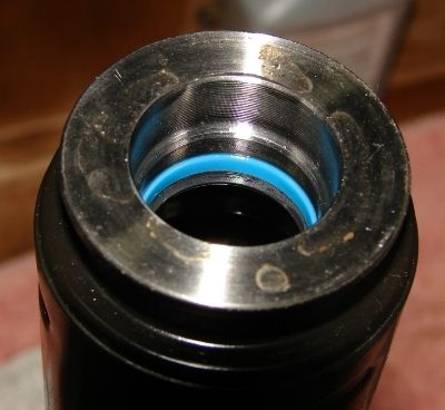
Install a new seal and o-ring on the gear housing cap. Use tape over the splined end of the pinion shaft and lubricate it with PS grease. Gently work the cap with seal over the shaft (support it near the shaft or it may turn inside out and release the spring that energizes the lip of the seal). Install the cover bolts and torque to 8 ft-lb.
Generously lubricate the rack guide with PS grease. Install a new o-ring on the rack guide screw. Install the guide, spring, and rack guide screw into the gear housing. Tighten the rack guide screw until it compresses the guide against the rack, then loosen it. Install the lock nut on the guide screw, but do not tighten it. Tighten the guide screw to 2.9 ft-lb, then back it off 20 degrees. Hold the rack guide screw in position as you tighten the lock nut to 18 ft-lb.
Install the inner tie rod stop washer (chamfered side out – tough to tell which side is chamfered), new lock washer, and inner tie rod ends into the end of the rack. Make sure the tabs on the lock washers engage the slots in the end of the rack. Torque the tie rod ends to 40 ft-lb. Bend both sides of each lock washer up against the flats on the tie rod end.
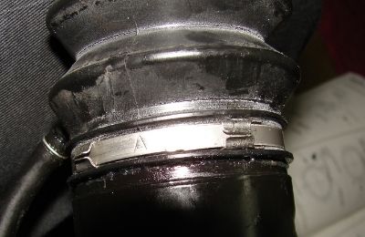
Lubricate the outside of the tie rod ends, the inside of the boots, and the small hole (for the threaded end of the tie rod) with PS grease. Install the boots over the tie rod ends. Install the spring clip on the small end. Install new boot bands on the large end of the boot. The band has a stiff end that anchors on a raised area near the first set of lock tabs; push then far end of the stiff section down, this tightens the band on the boot. Hold the band down and bend the lock tabs down to hold it in place.
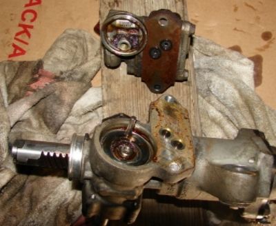
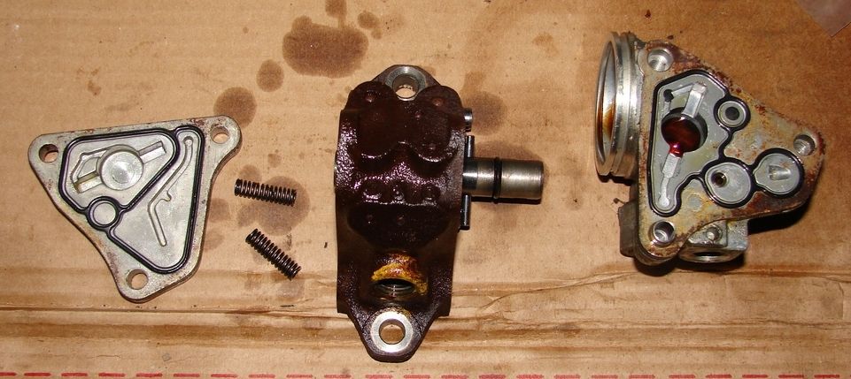
Remove the covers from the valve body. Be careful, there are two springs that may easily fall out. If they are different, it is hard to tell them apart. Edit: Checked Majestic's site. the two springs are the same part number. All the pistons seemed to move freely, so I did not remove them. Install new gaskets on the covers and a new o-ring on the large piston; carefully install the covers on either side of the housing. Torque the three bolts to 7 ft-lb.
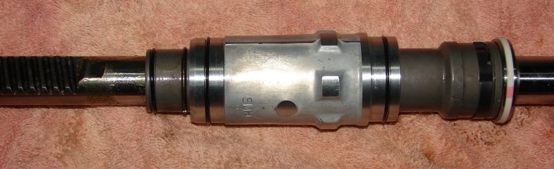
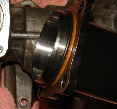
Install the orifices and new o-rings on the gear housing. Install a new o-ring on the port housing of the valve body; lubricate it with PS grease. Install the valve body onto the gear housing. Torque the bolts to 16 ft-lb.
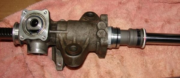
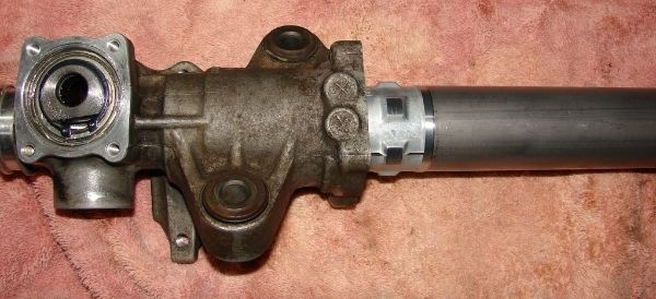
Viewing from the gear housing (left) end of the assembly, rotate the boot so that the vent tube nipple is at about 10:30 with the pinion shaft at 12:00. Viewing from the cylinder (right) end of the assembly, rotate the boot so that the nipple is at about 4:30 with the pinion shaft at 12:00. Install the vent tube to the two nipples. Also when viewing from the right, install the transfer hose clip such that the hook that the hose snaps into is at about 2:00. Install the transfer tube to the boot nipples and snap it into the clip.
Ready to go:
 DSC01418 by Paul Kemme, on Flickr
This procedure is to rebuild your power steering rack. This one was still working properly, but the boots were completely split open and the rack was leaking. I suppose it is easier (and maybe more cost effective) to purchase a rebuilt one; I had heard some horror stories about aftermarket racks, so I decided to rebuild mine with OEM parts. This procedure assumes that the power steering rack has already been removed from the car: http://www.cb7tuner.com/vbb/showthread.php?t=30228 I screwed up and forgot to take a few pictures along the way. It is highly recommended that you have the appropriate pages of the factory service manual available when doing this.
Tools needed:
10 mm socket
12 mm socket
14 mm socket
17 mm open end wrench
Crescent wrench
Snap ring pliers
Small chisel or punch
Flat bladed screwdriver
Large channel locks
Hammer
Supplies:
065A3-SM4-435 steering gearbox seal kit (6/21/2017: these kits may no longer be available from HONDA)
065B3-SM4-405 steering valve body seal kit
Inner tie rod ends (2)
Tie rod boots (2)
Tie rod boot bands (2)
Honda Power Steering grease 08733-B070E
Brake cleaner
DSC01388 by Paul Kemme, on FlickrReference figures from Majestic; I noticed that it doesn't show the pinion retainer:
Clean the outside of the unit prior to starting disassembly; if necessary use a tooth brush with brake cleaner or even a wire brush to remove caked on dirt.
Remove the nut from the inner tie rod. Undo the bent over tabs on the tie rod boot straps, remove the straps. Remove the spring clamp where the boot attaches to the inner tie rod end, then remove the boots.


The inner tie rods are secured with a bent washer, use a screwdriver or small chisel to flatten the bent portion of these washers.


Using a crescent wrench on the flats on the end of the rack and a 17 mm wrench on the tie rod base, remove the inner tie rods from the rack. If the outer end of the tie rod does not sag when holding the inner end horizontal, then it is probably still good. If you’re going to this extent, it is a good idea to go ahead and install new inner tie rods.


Remove the two bolts mounting the valve body to the gear box. There are two orifices in ports on the valve body that are not secured, remove them and put them where you won’t lose them. I like to use shallow cardboard boxes as project boxes to hold parts.


Use channel locks (or a large crescent wrench) to loosen the locknut on the rack guide screw; then a 14 mm socket to remove the rack guide screw, then remove the spring and rack guide.


Use the snap ring pliers to remove the small snap ring on the exposed end of the pinion shaft.

Turn the unit over and tap lightly on the end of the pinion shaft to drive the pinion shaft and bearing assembly out of the gear housing.


Using a 12 mm socket, remove the four bolts attaching the cylinder housing to the gear housing. This is spring loaded, so remove them evenly a little at a time. Separate the cylinder housing from the gear housing. There is a spring and Teflon bushing inside the end of the cylinder housing, these should pretty much fall out, but they may remain on the rack - remove them. From the right end of the outer cylinder, push the shaft seal toward the inside to remove it.


Slide the inner cylinder off the rack; then remove the rack assembly from the housing.

Remover the seal retainer and cylinder cap assembly from the rack. There is a snap ring on the seal retainer that keeps it from coming out of the cylinder cap; I didn’t see a reason to separate them – I could access the o-rings on both parts, so I did not remove the ring and separate these two parts.
Remove the four bolts holding the gear housing cap; remove the cap. (Note: this picture was taken during assembly; the pinion shaft is not there at this point of disassembly.)

Remove the snap ring on the pinion holder, then remove the pinion holder from the gear housing.

Everything disassembled:

Clean the old grease from the pinion upper bearing. Pack the bearing as best you can with new grease. Install the pinion holder. Install the snap ring on the end of the pinion holder.
On the rack, install a new piston seal. This seal has a triangular cross section, the tip should be pointed up. Install a new piston ring over this seal. There are Honda tools to stretch the ring over the piston, then to resize it. I warmed it with a hair dryer and was able to gently stretch it over the piston, then compress and straighten it with my fingers.


Remove the large clip from the seal retainer; remove rack bushing B and the cylinder end seal.

After greasing the rack surface, install bushing B on the toothed end of the rack against the piston. Honda has a tool to install the new end seal over the toothed section of the rack; I simply wrapped the end of the rack with masking tape, sticky side out, then slipped the seal over that. Slide the seal and tape over the rod over to the bushing. The open face of the seal should face the bushing.


Install new o-rings on the seal retainer and cylinder cap. Install the seal retainer over the seal and bushing on the rack. Install the retainer clip.

Install the retaining washer in the gear housing.


Generously grease the toothed end of the rack, lubricate the o-rings with power steering fluid (or PS grease) then install the rack with seal retainer and cylinder cap into the gear housing.

Generously lubricate the inside diameter of the cylinder with power steering fluid, carefully install it past the piston seal, then onto the end of the cylinder cap.

Lightly grease the non-toothed end of the rack. Install the spring and bushing A. Install the cylinder end seal in the end of the cylinder housing from the inside. I dropped it in, then used my finger from the outside end to position the seal. The open face of the seal should face inside.


Install the backup ring (you can reuse this part) and a new o-ring on the cylinder housing. Wrap the end of the rack in masking tape and lubricate the tape with grease. Install the cylinder housing over the rack and carefully guide the end of the rack through the seal. Push the cylinder housing into the gear housing and install the four bolts. Torque the bolts evenly to 16 ft-lb.


Generously lubricate the pinion gear and bearing with PS grease and install in the pinion holder. Install the snap ring to retain it.


Install a new seal and o-ring on the gear housing cap. Use tape over the splined end of the pinion shaft and lubricate it with PS grease. Gently work the cap with seal over the shaft (support it near the shaft or it may turn inside out and release the spring that energizes the lip of the seal). Install the cover bolts and torque to 8 ft-lb.


Generously lubricate the rack guide with PS grease. Install a new o-ring on the rack guide screw. Install the guide, spring, and rack guide screw into the gear housing. Tighten the rack guide screw until it compresses the guide against the rack, then loosen it. Install the lock nut on the guide screw, but do not tighten it. Tighten the guide screw to 2.9 ft-lb, then back it off 20 degrees. Hold the rack guide screw in position as you tighten the lock nut to 18 ft-lb.

Install the inner tie rod stop washer (chamfered side out – tough to tell which side is chamfered), new lock washer, and inner tie rod ends into the end of the rack. Make sure the tabs on the lock washers engage the slots in the end of the rack. Torque the tie rod ends to 40 ft-lb. Bend both sides of each lock washer up against the flats on the tie rod end.


Lubricate the outside of the tie rod ends, the inside of the boots, and the small hole (for the threaded end of the tie rod) with PS grease. Install the boots over the tie rod ends. Install the spring clip on the small end. Install new boot bands on the large end of the boot. The band has a stiff end that anchors on a raised area near the first set of lock tabs; push then far end of the stiff section down, this tightens the band on the boot. Hold the band down and bend the lock tabs down to hold it in place.

Remove the covers from the valve body. Be careful, there are two springs that may easily fall out. If they are different, it is hard to tell them apart. Edit: Checked Majestic's site. the two springs are the same part number. All the pistons seemed to move freely, so I did not remove them. Install new gaskets on the covers and a new o-ring on the large piston; carefully install the covers on either side of the housing. Torque the three bolts to 7 ft-lb.

Install the orifices and new o-rings on the gear housing. Install a new o-ring on the port housing of the valve body; lubricate it with PS grease. Install the valve body onto the gear housing. Torque the bolts to 16 ft-lb.

Viewing from the gear housing (left) end of the assembly, rotate the boot so that the vent tube nipple is at about 10:30 with the pinion shaft at 12:00. Viewing from the cylinder (right) end of the assembly, rotate the boot so that the nipple is at about 4:30 with the pinion shaft at 12:00. Install the vent tube to the two nipples. Also when viewing from the right, install the transfer hose clip such that the hook that the hose snaps into is at about 2:00. Install the transfer tube to the boot nipples and snap it into the clip.
Ready to go:
DSC01418 by Paul Kemme, on Flickr


Comment